Will the software inform us and prevent the job when this happens. I personally don’t see any major issue for me ( nothing specifically that large that I can think of where it would matter - and like many above comments I’ll take the depth trade off !), but curious if it this happens when laser speed is set higher, will the software say - “lower speed or reduce image”?
8 Likes
With an extra half inch in the Z, I see a rotary attachment in my future, just have to figure out how to sync it with the X axis. The new spec is Great News!
12 Likes
If the gf is as smart as I think it will be, there will be no need to sync up, just rotate x degrees and resume.
7 Likes
On everything I’ve been considering creating, my biggest concern was the limited material thickness. Sounds like an agreeable trade-off to me.
8 Likes
Yeah I’m good, a bit more z is what I was needing anyway.
5 Likes
Indeed. And because I know you’re all thinking it, we’ve already put in the feature wishlist hopper a “spin around alignment” feature so you can do just that on Basic. But see below for a caveat.
Yes.
Good question - it’s close to the front, but there’s probably 1"-2" of dead zone (I’d have to check). So if you did a flip-around cut, you might get 14-16", not 18" of printable area.
Here’s an excerpt from the pre-release letter that talks about it:
Work Area
20” x 12” working bed. Maximum thickness of material with tray installed is 0.5”.
Done: 20” x 18” working bed. Printing area of 18.5” x 10”. Maximum thickness of material with tray installed of 0.5”, maximum thickness of material with tray removed is 2”. Focus range of 0.5”.
To do: When the laser is moving at maximum speed, it needs room to slow down near the top, bottom, and both sides. We’ll be updating the software to compensate for that so it can give you more working space - up to 11.5" x 20.4" for slow movements like cuts; a little bit less for faster motions like engraves.
Bonus: Our original specs for thickness were 1.5” with tray removed - we were able to increase that to 2.0” for you.
It throws up curtains that show you where you can position your image. Notification (‘you could slow this down…’) is a good idea for the hopper.
30 Likes
Thanks for the update!
I’m going to echo a question that a few people have already asked.
How will the 11.5in work area be positioned on the 18in part? Will it be centered or offset to one side?
Edit: You answered my question just as I posted this. It only took me half an hour to realize.
8 Likes
Pardon me while I squeeeee! ![]()
![]()
![]()
![]()
![]()
(A feature like this would make the rotary device I have in mind feasible.)
Hey @dan …feel free to throw out some more bad news…I’m liking it!
13 Likes
Thank you! Fixed that.
9 Likes
So for a unit sold as 12"x20", we’re actually getting roughly 14"-16" x 20.4" of printable area. Oh boo-hoo, you just keep coming up with “bad” news any time you like. ![]()
19 Likes
Cool, so Pro units just became much more attractive as an upgrade then. But even for the basic users, they can put larger stock in, however cannot cut quite as large of a single piece at a time.
The best I have thought of is that you suspend your rotary attachment from the gantry, but have large wheels which will roll along on the floor of the Glowforge. This makes it so that when the gantry moves up or down, it causes the wheels to turn and thus rotates your object for you.
Finding the exact proper position so that you rotate at the correct rate will be the tricky part of this.
OOH. So actually a basic Glowforge can cut an item LARGER than the originally slated 12", it just involves a manual flip and re-registration of the piece. Nifty indeed.
Also, I assume that the slowing near the edges has a corollary of: Always try to place your smaller object cut/engraves near the middle of the bed for maximum available speed.
13 Likes
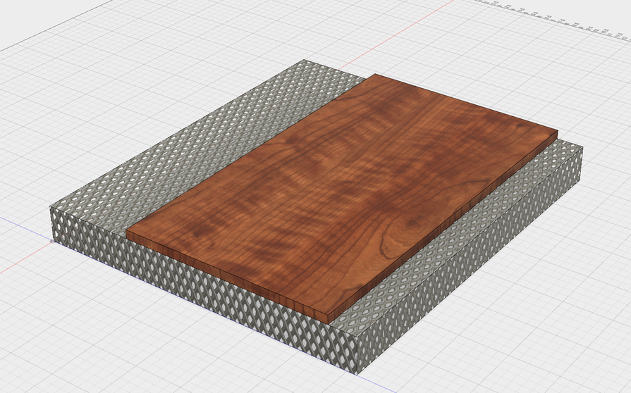
quick illustration this is scale the mesh is the bed(and or dead space that the cabinet can hold) to @dan new spec, the wood indicates where the laser can laze based on the new spec.
let me know if I have interrupted incorrectly
the off set is 1.5 inches from the front splitting the diff between 1-2 @dan
down side to 18 inchs… my brother only has a 12inch planner ![]()
13 Likes
psh better scrap utilization, mark a line cut it off etc make it works means having to break down sheets of plywood less its good news for stock managment we just need to keep single parts less then 11.5x20.4 unless they get off set registration working then bam we got a upgrade
1 Like

Yeah but move the wood forward a little. The lazeable area will not be centered fore/aft.
4 Likes
Correct!
Also a good idea generally, as our lid camera is sharpest near the middle.
The board would be much closer to the front than the back - 1-2" from the edge (I don’t know offhand).
Well, it’s a long read at least. ![]()
21 Likes
I came to the same conclusion, but I wasn’t stressing about the Z-axis at all.
I was thinking of a “U” shape carrier that you place under the X-axis beam, with double-wheels counter-rotating the object as it moves Y-axis. The gantry could rise/lower between the arms of the “U” as required for focus.
At least, that’s how it makes sense in my head. I don’t believe any special math tricks would be needed to account for Y-axis rotation, then.
2 Likes
Ugh… re-reading myself in the quote I can barely figure out what I meant.
When I said “moves up or down” I meant as the whole gantry moves along the Y axis. So when the laser thinks it is moving to another Y coordinate on a flat piece, it is instead getting a different Theta coordinate on your curved piece.
1 Like
Ha! Okay, your plane of reference was different, but I think you and I are talking about the same thing. 
2 Likes
I can only hope I’m lucky enough to get to read it!
5 Likes