But we have to be back for our appointment at 7 on the 7th.
2 Likes
Great video.
I do have a question though. When the picture is resized and placed within the original eye, it appears Dan puts it directly in the middle of the eye.
When the glowforge cuts it appears to do the new smaller eye to left of the larger wood eye. Is this a registration error? Trick of perspective?
Dave
Dan mentioned they’re working on the registration when someone else brought up the same thing.
1 Like
There was some lengthy discussion about this, and @dan was eventually asked directly how we would accurately register material if we don’t just “eyeball” it with the camera’s image. He never answered.
1 Like
Sorry, thought I’d covered that.
The alignment techniques we use:
- Camera. (This covers 95% of cases, and continues to improve)
- Relative. You lay out multiple cuts and turn them on to print one at a time. The accuracy between objects is <0.001". (This is a little different than the other two, but it’s so important and used so often I want to be sure to include it).
- Template. Finally, if you want sub-millimeter accuracy, you create the outline of the object and engrave. You cut the outline in a piece of scrap, remove the cutout, and put in the object. Then you engrave. This is how I did my phone, for example.
You can also cut ‘permanent’ rails or rulers, but we’ve never found the need to do that. I’m sure others will experiment with other strategies.
14 Likes
@dan Question. This is something I’d like to see demonstrated. Something that is pre-made (and oddly shaped) Then engrave/etch something on it thats edge to edge.
i.e. A Project I did a couple months back had a bunch of parts cut out of 1/4" 6051. Then powder coat them. Then engrave/etch something within it. (which took many, many, many hours with a engraving endmill.)
Since I’ll have the CAD model of the thing what was milled, I want to be able to drop in the part I want the forge and line up the ‘actual’ with the part I want engraved.
How would one ‘target’ something like that with the Glowforge. The CNC side of my brain would touch off dead center of the part and make that my 0,0. But with the 'forge that’s done optically/magically.
To make sure my question is clear here’s a couple visuals.
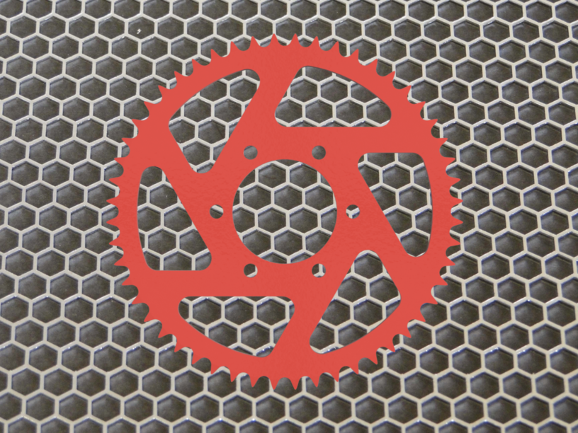
This is what the part would look like on the bed of the glowforge.
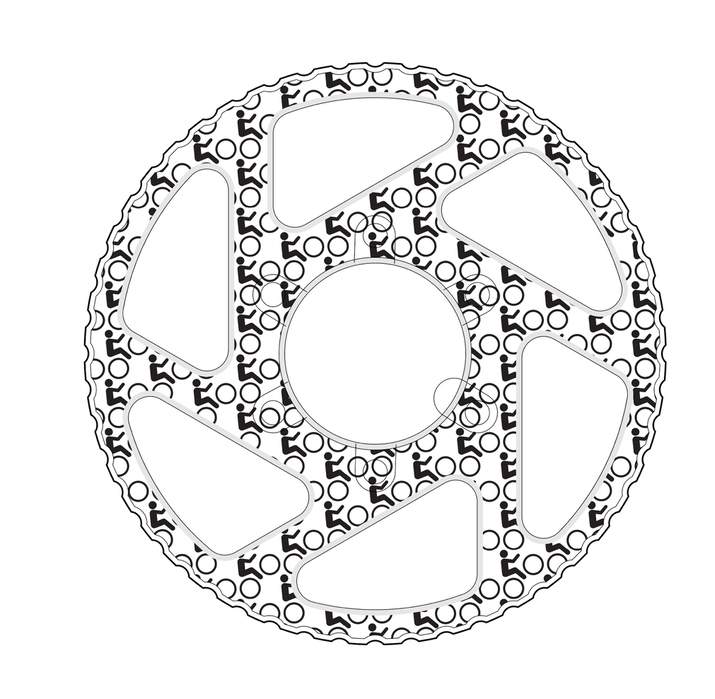
This would be the thing I would want engraved on it. The pattern sits within the physical part and it has ‘accent’ lines/patterns around it. (the gray band would be a low power pass to take off some of the powder coating but not all.)
Is this something that I am going to have to create a jig with a 0,0 reference spot so I can line up the vector with the part? Or does the 'forge cloud find the objects edges and auto locate the center of it?
5 Likes
You building a zoetrope?
4 Likes
No. That was part of a trophy.
4 Likes
As I understand @dan’s post regarding this, it would depend on the accuracy you want.
If you are wanting HIGHLY accurate, then you first load just the CAD drawing and run it as an outline cut only, and cut that from cardboard or wood (whatever you cut it from, it has some thickness to it, and is VERY well held in place on the honeycomb).
Then you remove the scrap material for the newly made jig, and you place in your actual object to cut. Now you run the full engrave (without the outline cut at all likely).
If you want fairly precise, then instead you just load in the image and manually position it over the camera image of the bed with your target object in place.
2 Likes
I saw that post too. I just wanted clarification from Team Glowforge on it. As it would mean that I’d have to make a jig for everything I plan on etching/engraving.
I guess this is the main difference between a traditional gcode driven CNC (Spindle, Laser, Plasma etc…) that honours G54 P<<>> and the glowforge. With that I can specify the fixture origin and/or material origin. Then have the op land where I want it. vs. either eyeballing it or having to design a fixture/jig for everything I plan on doing. I know it’s not difficult to do. Just additional work.
1 Like
How do you align your object with your defined 0,0 in the other methods? Unless you are already in possession of a jig that shows the 0,0, or you are placing the tool in contact with your material at the 0,0 you want… doesn’t it also boil down to eyeballing for the placement?
“Make a jig” makes it sound much harder than “Slap in some cardboard and test the job” for me. They both mean the same thing, but the second one is something I always do to see if the file works right anyway, and the first is new terminology for me, so sounded daunting at first.
Anyway… all of that is really semantics, and me not being familiar with other machinery and what you gain/how you accomplish assigning an origin. So what I am really curious about is how much more accurate (or how much easier) it is to assign an origin than to drag and drop on the lid image.
1 Like
This is what I have done as well, cardboard with a few good strong magnets to hold it down. It is surprisingly effective.
You can do that with any laser but according to revolutionary super power number 8:
The dual cameras align the laser head with
the frame, with your design, and with your material. Glowforge realigns
with every cut and engrave, adjusting timing and position, so every
print comes out perfectly.
It needs to be able to do very accurate optical alignment for the pass thru slot to be useful.
2 Likes
Thats how I do it currently. Was hoping the Glowforge would eliminate that…
1 Like
The difference is between highly accurate, and very accurate. I can think of few things where I need more than 0.001" accuracy. That is the case where @dan said you would want a jig.
So he hasn’t said “You need jigs every time!” He has just said “A jig is still imperceptibly better than the cameras”
1 Like
This is where spindle based CNC’ing is different. Eyeballing causes spindle crashes, broken endmills & tears.
Jigs & Fixturing are things I take seriously. Measure 100x cut once. Especially when I am cutting/engraving one offs or double sided ops. Nothing sucks more then screwing up a 4.5 hr op cause something shifted. Once I pick the 0,0 in the CAM. I use a dial indicator to check the stock to make SURE it’s square to the machine. Then to locate either the edge of the center of the stock material.
Then set my G54. Then use the stock offset probe to se the Z height.
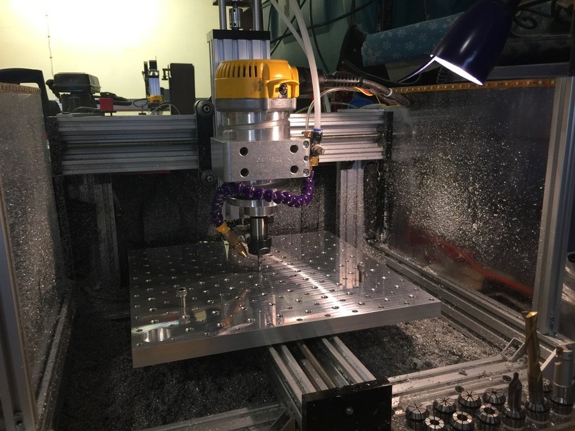
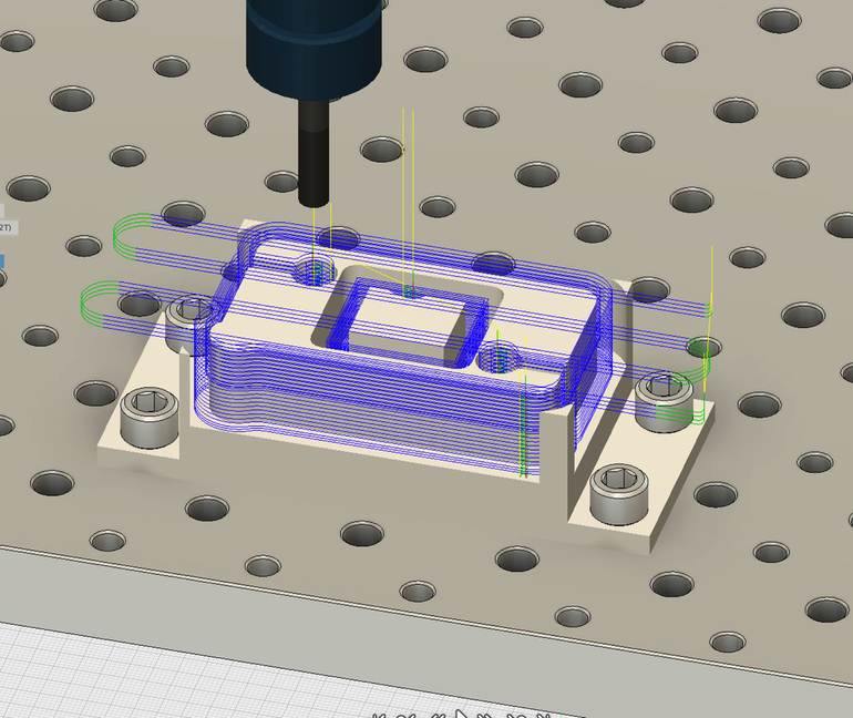
This is the mini pallet I have on my smaller CNC.
The mini pallet is a model I have in Fusion 360 which is used as a ‘virtual fixture’. This way I’ll how to efficiently mount the stock material before I step foot in the garage.
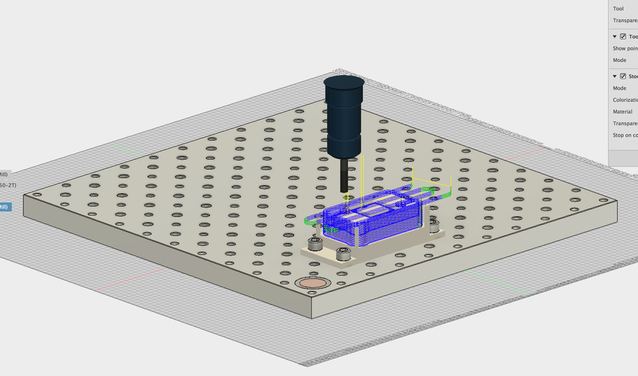
The CAM will now where/what it is and will tell me in the simulator if the endmill makes contact to anything except the stock material. (i.e. the M8 socket head bolts) or plunges to deep.
Jigs & Fixtures I can do. Was hoping the Glowforge had a more sophisticated solution for finding objects and zeroing up a vector on a object
7 Likes
Alright, so no eyeball ever, just loads of measurement.
The glowforge not having any sort of defined home position makes it impossible to define by measurement. So it would all be down to using the camera positioning with the detail zoom, and hopefully some software controlled “Snap to border” type of controls. Or cutting on material which is fixed in place to outline the area in which to place your actual desired cut.
So given the amount of measurement for the jigs, possibly not more work, just different work. But hopefully sufficient accuracy by camera alone to result in an end result of less work and less material consumption.
2 Likes
Did I miss this information? Strange…both my lasers have a 0,0 position which is changable to anywhere on the bed…
1 Like
Well 0,0 will exist but I get the impression that we will not be dealing with it due to the cameras doing so much of the alignment work.
2 Likes
Dan had responded once to a question about if we can define a 0,0 by saying that the question is meaningless in terms of the glowforge.
Obviously there has to be a left/top most point to which the stepper motors can move the cutting head, and hopefully there are some limit switches in as a backup system. So there should still be SOME 0,0 point… but I see the idea that having a drag and drop interface and a camera making it reasonably pointless to bother showing anyone an actual grid upon which to measure, or including a numeric control for positioning (even if my brain does work by numbers and not images, and it kills me not to have them)
4 Likes