Acceleration/Deceleration power fluctuation

I have noticed, when cutting multiple materials, that I get inconsistent depth of cut which results in:

  • pieces not being cut free in sections when power is too low
  • or excessive charring/burn through when power is too high.

I have also noticed the latter using ProofGrade stock which uses barcode presets.

The problem is best exemplified when cutting foam-board because this material is very consistent in density and most indicative of power fluctuation. The following pictures show curves generated by NURBS CAD software that was printed to PDF and uploaded to the Glowforge app. The PDF files are tiny taking up a few KB and appear to be passing clean curve data rather than interpolating curves as short straight lines.


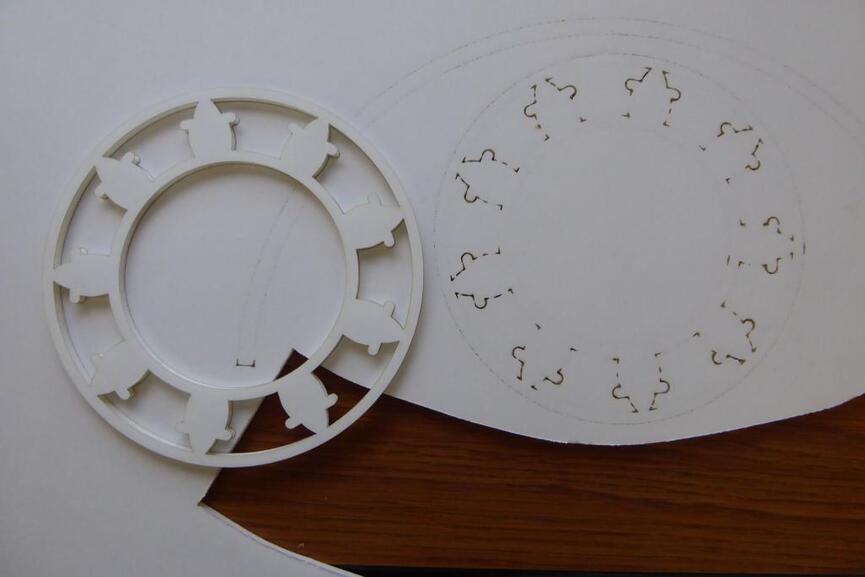
This pictures shows a successful cut out of piece, on left, where power was sufficient to cut all the way through. The board underneath shows the same piece from the underside where power was not sufficient to release the piece.

FYI, This piece is a simplified representation of a 9 cylinder radial engine. All cuts use the same settings and are split across three layers.

The 1st layer is interior circle which is cut as one continuous curve starting & ending just south of east and appears as a short dash on the underside cut visible on the right. Note that start/end cut within 1/4" start/finish cuts all the way through but the rest of the circle does not. This is problem #1 - where start/end of curve cuts deeper then rest of continuous curve.

The next layer cuts the voids between cylinders with Glowforge cutting again as one continuous path per void. This is where the acceleration/deceleration problem become most apparent. Same cut settings but you can clearly see that corners and tight radius arcs are cut all the way through (burning back paper in corners/tight arcs) where as lesser angle arcs do not cut through.

Finally the exterior circle is cut on 3rd layer, again using same preset, and almost makes it through. Note that this exterior circle cuts deeper than the 1st tighter interior circle using same preset.

I ran many test cuts and the power/speed setting produced greatly varying results using tiny variations in power/speed settings.


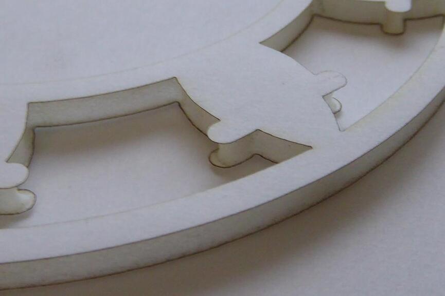
This picture shows the best results I got which shows heavy foam melt on tight radius arcs (almost picture center) and little to no foam melt on larger arcs, interior/exterior circles using the same settings.

Does the Glowforge app adjust power setting when accelerating/decelerating the cutting head?

I understand that foam-board is not a proof grade material but the same thing happens, to a lesser extent, on PG medium board, so the problem is the same.

If so then acceleration/deceleration ratios should be adjusted to accurately compensate.

4 Likes

In a word
No
in a lot more words
Not yet
It is a very well known issue exacerbated the faster the base cutting speed.

Engraving will apply room for acceleration / deceleration which is why the cutting area is reduced, and reduced more the higher the speed. If it is extremely important deep engraving can be extremely slow but corner burning ceases to be an issue. One of our number was making tiny branches and leaves in paper and that turned out to be the best way not to burn off the leaves at the base,

I had a similar problem and was able to solve it with small curves where there had been hard corners, and a different time by leaving gaps in the line that the laser would shut off during the gap without changing direction.

If you go to boxes.py for design the lines do not connect so the overburn from stopping is partially accounted for.

The only solution beyond that (and it is less of one) is to lower the speed and power settings so the change of speed around a corner is as minimized as possible but as yet such calculations for accelerations would so increase the calculation time needed and file size of the result beyond acceptable limits and still only be an approximation of the need.

8 Likes

Very good point. Breaking your object into individual lines makes quite a bit of difference.

1 Like

Thx for the input.

Has this been confirmed by Glowforge staff? If so then it is a design flaw. If the speed is reduced and power is not then obviously it will cut deeper.

I am using joined lines to avoid another issue which is start/stop of line double burns a point which I think is the same thing that @rbtdanforth called ‘corner burning’ or ‘overburn’.

I will try this as one of the CAD programs I use has a fillet curve command which can be applied to multiple curves at once. In my case a lot of parts interlock so rounding corners will introduce problems. I am skeptical that this will work as the 1/8" radius in pictures is already going too slow.

I can see this working and something like this should be automatically done by the app. I tried to find some commands in programs that could do this automatically but have not found any. Don’t suppose you know of any way to do this in bulk?

Yes this certainly does work but really increases the cutting time considerably. Basically have to reduce speed to around 200. This can be a problem on thin/soft materials where speed must be high because even at lowest power setting it is still too much.

Is deceleration/acceleration required for the glowforge to operate?
If not then having an option to turn it off would be great.
If yes, then I really don’t see a solution other than reducing power when reducing speed.

Yes, it’s physics.

2 Likes

Well, yes and no. The start and stop and sharp corner burns could be fixed - in fact they are when engraving. You keep the head moving and turn the laser on/off at the ends of lines.

You need to be a bit clever about how you handle corners, but that is the beauty of cloud software, plenty of power at your disposal.

This is exactly what engraves do (hence the borders).

What you really want is something which:

  1. In general, gets the head moving and as it reaches the start of the cut turns the laser on
  2. Starts cutting from the edges because I think the acceleration over burn is less and I want maximum cutting area
  3. Works out when it can handle an obtuse angle (or curve) and when it is too acute. (too acute varies by speed).
  4. When it is over acute, you over-run the head, turn the laser off at the stop point, circle back round to the new direction for the next part of the acute angle.

This is all back to optimising cut orders and head movements - something the team seems to not want to tackle at all. Which I still don’t understand because its not that difficult. I haven’t looked but I wouldn’t be surprised if there is not some open-source of maker developed algorithms available for this. Heck, it’s not my area of expertise but I reckon even I could write this.

I have a suspicion that there is no-one on the team who’s job it is to improve the actual lasering part of this whole process - which is why we get tweaks to the UI and internal sensors and stuff but no actual changes to the lasering part.

I understand the theory behind accommodating for it. One can also design lead-ins and lead-outs, like is often done in industrial design. This also eliminates the pierce part of the equation.

1 Like

Right that is what I anticipated when using ‘engrave’. That setting seem to optimize power/speed based on output resolution.

Please can you explain how I could be clever and use cloud software to fix his?

Edit - bad attempt at humor. Sorry.

Yes, CNC Lead in/out principles seem to be applicable and should at least be implemented in automated power settings when changing speed.

Thank you for sharing this topic! It sounds like this would be covered by creating a new feature. We haven’t announced anything along these lines yet, but I’ll send it to our product team as a customer request.

I’m going to close this thread - if you have any other questions, go ahead and post a new topic. Thanks again for letting us know about this!

1 Like