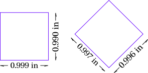
Using a drawing with a 1.000 inch square to test for the kerf in 111-03 Proof Grade Acrylic, the following dimensions are found after cutting:
Since most of my finger/slot joints use the non-rotated orientation, would you use two kerfs, one for x-direction paths and a different one for y-direction paths?
That’s interesting. Maybe it’s more about the way that lines are interpolated and converted to X/Y coordinates than there being some major difference in kerf?
Maybe it’s some difference in speed when running at 45 degrees versus orthogonal? If it were slightly slower on the 45 it could lead to wider kerf.
Was it on the same sheet of acrylic? Sheets can vary, normally I’d say it’s not a serious concern but you’re chasing three or four thousandths, so it’s something to consider. Hmm.
I just cut a few random squares and measured the variance to be around 0.005" - with no discernible pattern whether “straight” or “rotated”. Specifically, there was that much variance between straight ones, and rotated ones.
This isn’t a precision industrial-quality machine. It uses rubber bands to control the motion, depending on where the teeth and notches are in the belts, there’ll be some slack/give. Has worked (for me and many others) for years.
Keep in mind, the beam itself isn’t vertical in most cases. Slack/tolerances in the way the carriage plate moves mean there can be quite a bit of “lean” front-to-back. That’s been discussed here if you want to search for it.
Same sheet of acrylic with spacing as shown in drawing. The cast acrylic should be homogeneous material, possibly better than extruded. This was Proof Grade beta.
FWIW, cast acrylic can have up to three times the amount a tolerance as compared to extruded, and with some manufactures, the same sheet of cast can have a tolerance of up to 25% or more from one end to another. So unfortunately cast isn’t homogeneous and it is possible tolerance is a factor.
The first two cuts were taken near Home position: (3,-2)-(x,y) inches on bed.
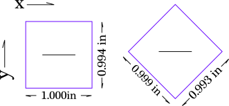
For a second location taken at ( x,y)~ (18,-11)
So the kerf varies from 0 to 0.007 inches. Acrylic thickness varies by 0.0015 icches between the two locations.
Whatever is causing the change in cut dimensions makes getting good joint fits almost impossible in acrylic. I am suspicious it is the Glowforge itself.
This is interesting. I have some 6mm white opaque acrylic I can test out tomorrow and see what my machine does. It is a very fine kerf in this particular acrylic. I’ll give you some more data points.
I have also tried Proof Grade Medium Density Draftboard. Looking at two locations on opposite sides of the bed, kerf varies from -0.003 to 0.007 inches. The negative value means the cut one inch piece was larger than the drawing. Afraid this could be a machine positing problem rather than a material issue.
I don’t know what this means. My calipers is in good shape. There is some skew as I can see daylight in between the jaws and the side of the coupon. I didn’t track which way I measured but that would be good to understand where on the bed these measurements lie. Anyway, not off by much.
Good data. My calipers are Mitutoyo dial with smallest fiducials at 0.001 inches. No gap between closed jaws.
Today I made cuts on PG Draftboard with a circle geometry. This allows orientation dependent measurements with a single piece. I think I will submit this problem to Problems and Support. Maybe they can download machine-specific corrections?
Thanks for getting more data.
We can brag on tools all day long (I have a 12" Mitotoyo here next to me on my sofa side table and a set of TESA micrometers in the room where my GF resides) but you’re missing the point.
The GF uses rubber bands to control the motion. You’re chasing precision it simply wasn’t designed for.
A thou or five is just fine for any kind of tab/slot/notch fitment on the materials it’s designed to cut. As stated earlier, the carriage plate is nowhere near horizontal and as a result, the beam is off by that much in either direction.
This is a second Glowforge machine. First one bought back in 2015 seemed to have less spread in kerf dependence on location or orientation.
Machine specific corrections for the drive belts would seem possible with downloaded error-correction data.