I was going to link to another topic that has (once again) disappeared, so be sure to check out the tutorials on kerf from @smcgathyfay and @Hirudin for a discussion of what kerf is, and how it impacts design.
If you’re just getting into Fusion 360, a good way to pick it up quickly is to watch a few of the Fusion 360 Training tutorials on YouTube:
.
.
.
Okay adjusting your sketches for kerf is fairly easy. If I had something like a hole that had to hit an exact diameter after cutting, I would probably do something like this:
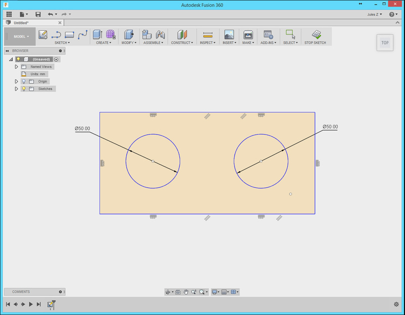
Open the dimensioned sketch.
This shows the exact size that you want things to be when you’re done. 50 mm hole.
.
.
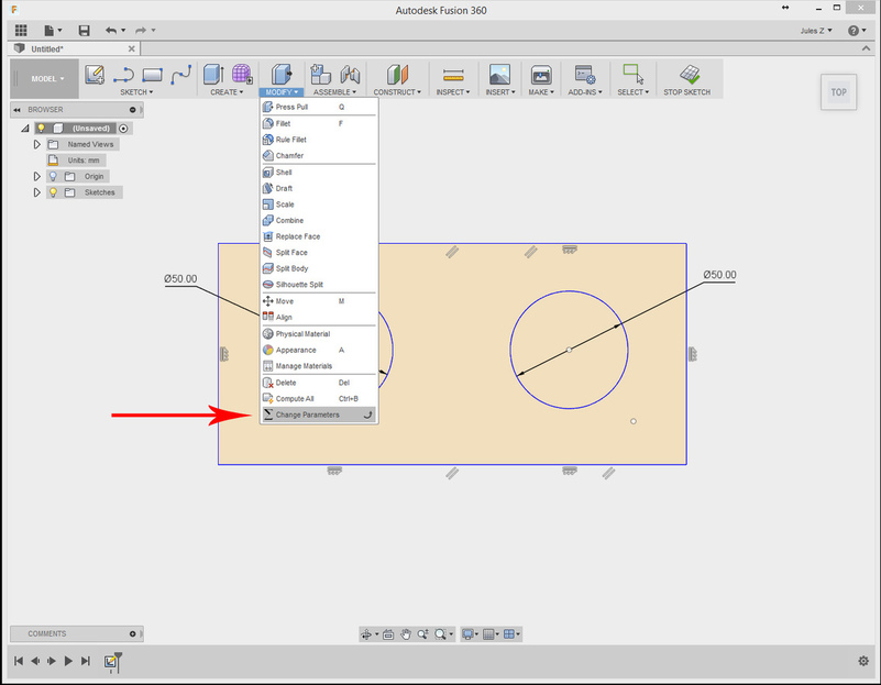
Modify > Change Parameters
.
.
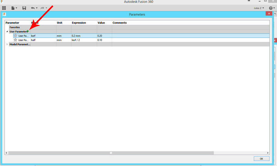
Create two new User Parameters by clicking on the green plus sign to add them:
-
kerf
Expression = 0.20 mm -
half
Expression = kerf/2
(You can also just name these “k” and “h” to speed up the typing once you’ve done a few.)
Click OK to save the values.
.
.
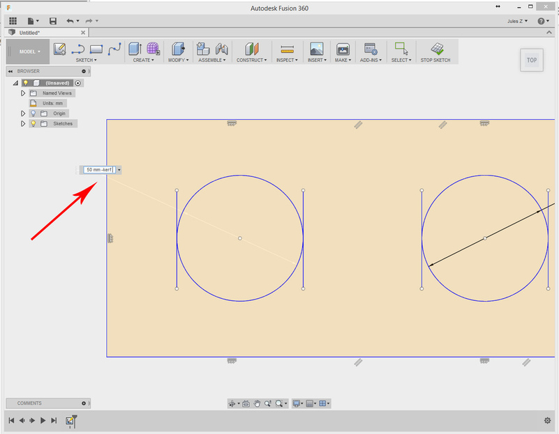
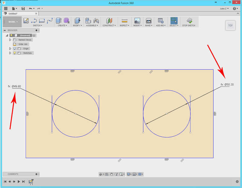
Select the dimension for the circle.
(The index lines are added here for display purposes only, to show the original size desired.)
If you want the hole that is being cut to remain the same size, change the formula to read:
dimension - kerf
If you are cutting out around the post in the center of the hole, change the formula to read:
dimension + kerf
.
.
If you now export the DXF of the sketch for use in the Glowforge, you will have adjusted your holes for a kerf of 0.20 mm. You can use that DXF on any non-Proofgrade material.
.
.
If you find out later that the kerf on that material is actually 0.25 mm instead of 0.20 mm, you can now go into:
-
Modify>Change Parameters and change the kerf Expression value to 0.25 mm.
-
Everything instantly adjusts automatically
 – export the DXF.
.
.
.
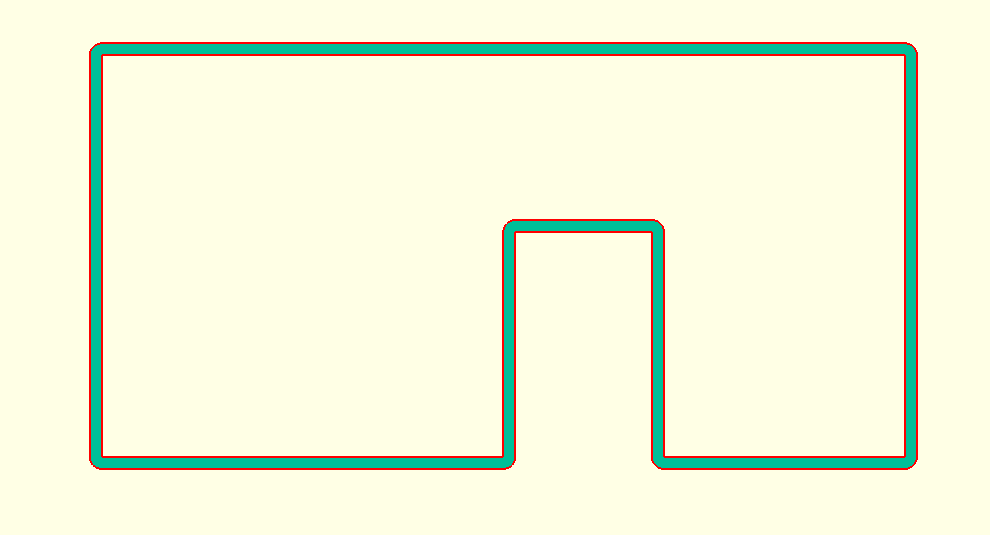
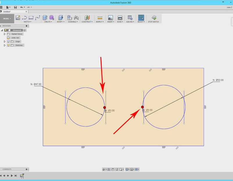
So you can actually see what is going on here – let’s bump the kerf to 3 mm:
(And I’ve added a little centered red laser dot equal to the kerf to show the edges of the path. Again, just for display.)
.
.
Kerf = 3mm
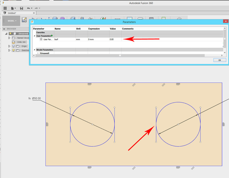
And when you’re done, or want to use Proofgrade material:
Kerf = 0
Back to where you started. Nothing destroyed. Nothing changed.
Alternate Method:
Choosing to cut outside of a shape like a CAM toolpath does.
Making this parametric requires an additional step or two, since the Offset is actually a new line creation, not a modification of an existing path.
(And you’d better believe it took me a while to figure that one out yesterday.)![]()
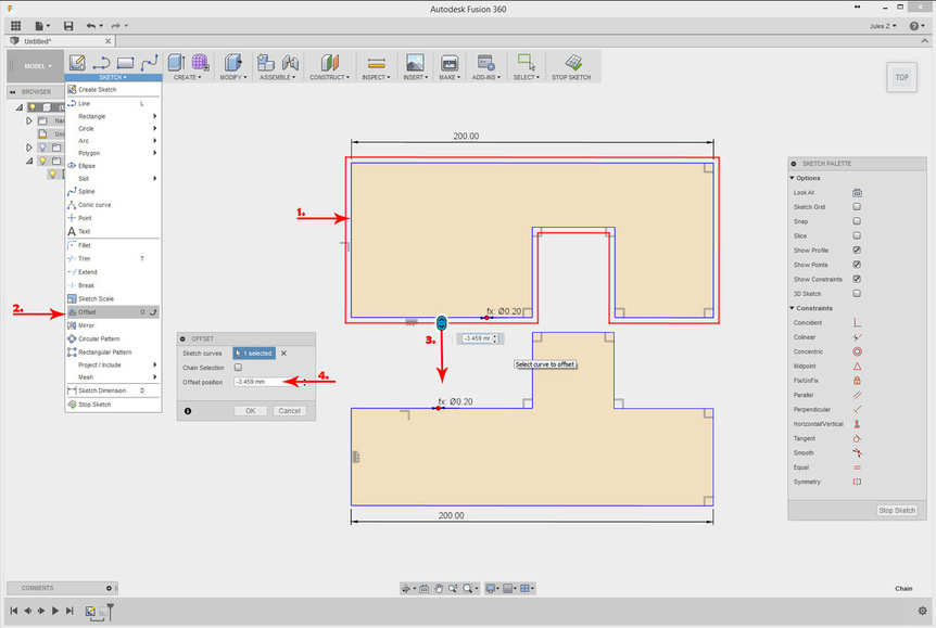
The steps are:
-
Double click on one of the lines in the closed shape to select all of the paths in it at once
-
Sketch > Offset
-
Drag the slider in the direction that you want to shift the path (Outside if you are cutting around a shape, and you want to maintain the exact dimensions of that shape. Inside if you wish to maintain the exact dimensions of a hole in your shape.)
-
Don’t worry about the value of the Offset position yet – you are just creating a template.
-
Click OK
.
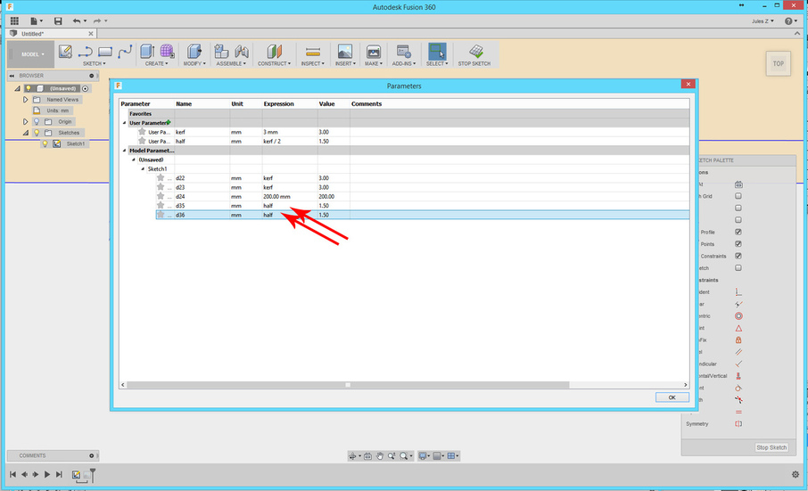
- Hover the mouse over the dimension for the relationship that you just created. Make note of the name of that dimension : d35
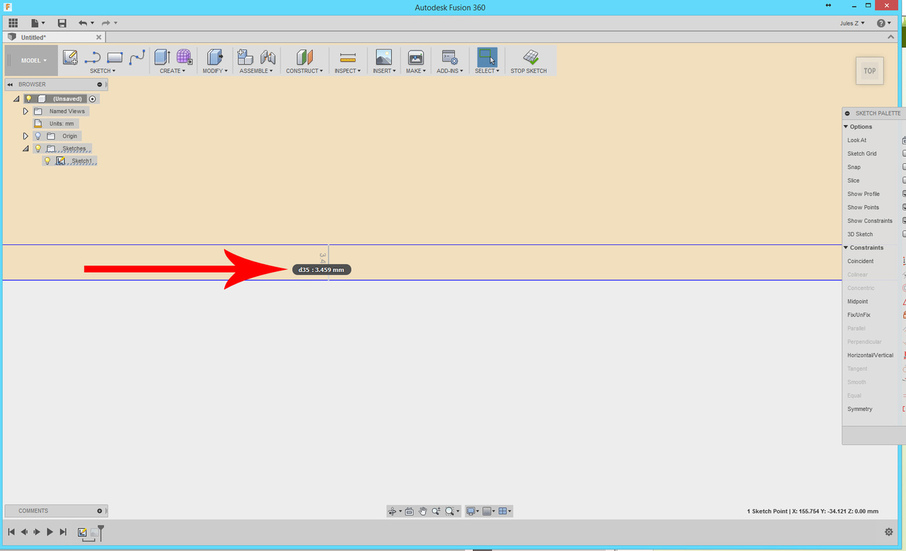
-
Go back to Modify> Change Parameters and drop down the Model Parameters list.
-
Change the Expression value to half for d35. (And any other offsets you have created.)
(You’ll see the value change to reflect the parameter value up top in the User Parameters section.)
- Click OK.
That’s it! You can now drop in one kerf number, whatever it is, and your file is going to adjust itself to cut correctly, without you having to tell another program that you want this line to cut on the inside and that one to cut on the outside!
Export the DXF, and you’re ready to convert it for the laser.
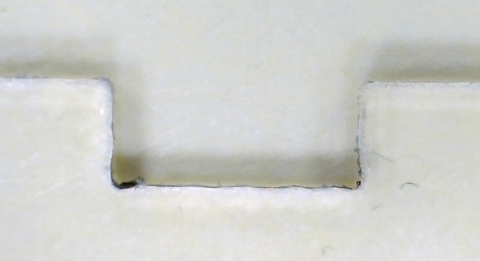
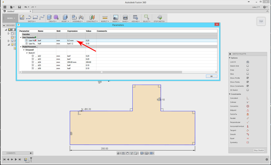
Some examples just for show:
For kerf = 0.20 mm (actual laser kerf)
.
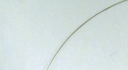
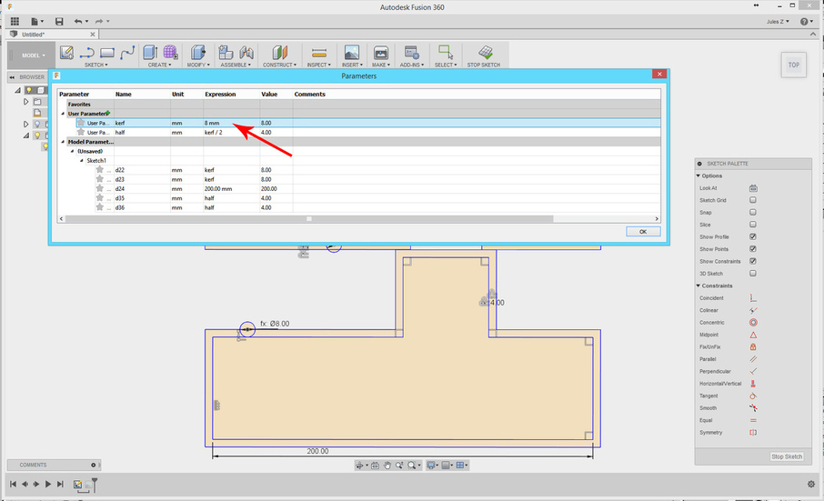
For kerf = 8.0 mm (big enough to see)
.
.
And when you’re done exporting your results for conversion, to go back to your single lines, the ever popular kerf = 0, and your file is back the way it was when you started.

.
.
Tips to speed it up:
When you are setting up your Offset templates for these things, this particular program requires you to do them one at a time, but you can speed up the process nicely by doing them all in one big batch, so that the names of the offset functions are numbered sequentially. Then just find one and you can change all of the Expressions to half at the same time.
(It saves a lot of flipping back and forth.)
Right mouse click, hold, and drag straight up to repeat a function. That’s just the way Fusion 360 works, but if you’re setting a lot of Offset templates on a bunch of different parts on a page, it saves a lot of clicking.
Okay a couple of comments, which I claim the right to, by virtue of having taken the time to put this together.
![]()
If you’ve read all the way through to this point, you’re interested in how kerf-adjustments are going to work, but since this is a tutorial, let’s please not clutter up the comments section with arguments for or against Glowforge doing something similar with their interface. Go argue whether they should have one or not in the other thread, where your vote can be counted.
For newcomers to 3D design:
Without going into a scary amount of detail - I’m going to point out that this kerf “fix” only addresses 2 of the 3 dimensions that you have to take into account in your designing. The third dimension, thickness, also has to be accounted for in your designs, and this method does not address it.
You do not want to see what that involves. ![]()
And last: If I’ve misunderstood what you guys are trying to accomplish…sorry about that. This was new to me yesterday.
Feel free to clarify. ![]()