There is generally some distortion due to the fisheye effect from the lid camera, but that does look like a lot. Did you correctly enter the height of the cardboard on the tray into the Unknown Material slot?
1 Like
I can also see that you have some stuff beneath the cardboard at a few points. Any tilt in the material will greatly exacerbate distortion.
Seeing as that the overlay is over half an inch off, I’d have to guess the material height is off quite a bit?
1 Like
As Jules said, and that would be very difficult to “sort the problem” out due to the distance of the camera to the print area, would be impossible to fit it all within a no super wide angle lens/camera.
If I understand, that is a post-op image? Didn’t it print where you originally placed the file (within the 1/4" tolerance).
The after image from the camera is always distorted. If the material hasn’t been moved, you could run the file again and it would score in exactly the same place - regardless of what the after image shows.
I notice the file image falls short on both sides, but the center is right on. Camera distortion… unless I misunderstand.
1 Like
I don’t believe this to be true. And it shouldn’t be true. I know that support also asks for after images to determine camera accuracy (you can actually figure it out exactly if you screenshot the rulers, calibeate a measurement length in Photoshop that corresponds to 1” on the rulers, and then do a measurement - it will give you the exact offset distance).
1 Like
It has always been true for me, granted that is from just the two machines I have used, and I have seen numerous examples here from user images.
So after you run a file the file image on yours lines up with the actual print?
1 Like
No, definitely doesn’t line up. I’m on the verge of out of spec, actually, if not out of spec. But there is not a shift in the after image: in that the material and the overlay is the same as the before image, it just shows the cuts. Does that make sense? Basically, I’m just saying that the offset in the “after image” is the same as the “before image” - you can run the job again, and it will hit the material in the exact same place (like you said), so by this, you can measure the actual offset of the overlay to the cut.
I don’t think I’m doing a very good job of explaining this… 
1 Like
Maybe “shifted” would be a better descriptor than “distorted.” I expect the actual cut to be shifted from the artwork due to the ‘up to 1/4" off’ thing, but if the after-image is a different size than the artwork, that tells me the material height was wrong.
1 Like
That got it across, thanks!
(I think your explanation was fine, just my comprehension is it problem)
I see what you mean. Incorrect thickness would result in an image like that.
In the post images of those thousands of tokens I did, the file overlay looked like the OP picture. The sheet of token images were inset to the left, and the right, with the center tokens dead on.
That was with the proper height as set by proof grade material selected. I would engrave and cut one side and then flip them in the cutouts. Image was off as described but the engrave was dead-on.
Yeah, individual parts will be shifted, but not stretched/distorted. In the OP photo it looks like the print is larger than the original, which I’m pretty sure has to be a material height issue.
Yes, my before camera image is the same as the after camera image, with the addition of seeing the newly lasered cut marks. I will run a few tests in the next day or two and report back. I’ve tried to be pretty careful to always measure and enter the material thickness, but it’s certainly possible I mussed something up along the way!
@jbmanning5 The material is sitting flat on the honey comb cutting bed. There’s a piece of 1/8" aluminum flat stock on the left edge acting as a stop for the material, and there are several magnets with some duct tape around them on the left and bottom edges, but nothing is under the material tipping it in any way.
Thank you for the responses.
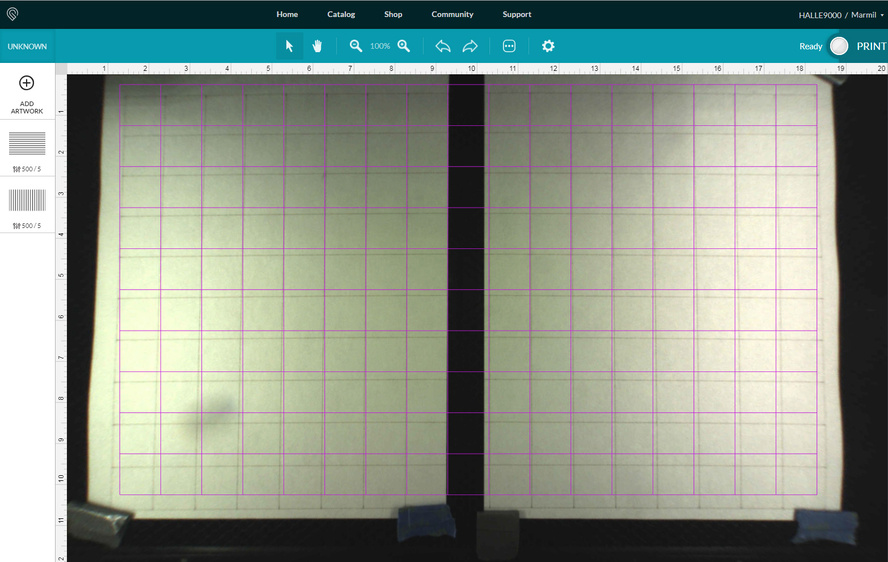
I made a 1" x 1" grid and ran that on some sheets of paper at full speed and with just enough power to make a bit of a visible line. I screen captured the GF UI once the job was done and the camera updated to show to cut lines.
This first test was with the sheets of paper directly on the honeycomb cutting bed. I measured and set the focus and also the material thickness to .005 inches.
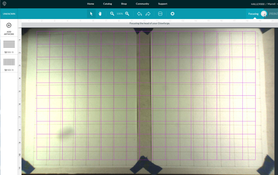
For a second test I put a few layers of proofgrade material down on the bed and then some new sheets of paper on top of that. I measured (all layers together) and set the focus and also the thickness to .257 inches.
Measuring the lasered grid on the paper gives totally accurate 1" x 1" squares. There’s definitely some sort of a trapezoidal warp to the camera image though. And the shift seems further off with the “thicker” test.
That definitely looks out of spec to me. For official verification, I’m pretty sure support will need to see a Gift of Good Measure cut from medium PG draft board. I’d do it down at the lower right where things look the most “off.”
On the bottom, I measured around .45 to .55" for your bottom image at the worst parts (to scale with the UI rulers).
Mine has a trapezoidal shift to it as well, unfortunately. Some of the things that you can check though are:
That the crumbtray is inserted correctly, which includes:
- the flat, plastic piece goes towards the back of the machine, not the front (several people have made this mistake);
- that it’s correctly and fully seated in the divots on the bottom of the machine;
- along with being seated correctly, make sure no waste material is down there in the divots (crud will definitely work its way down there);
- that there is no waste material (dust, flyaways, etc.) that are caught in the hinge of the front door, which can affect how the lid closes;
- that the lid closes fairly smoothly, it shouldn’t really scrape heavily, etc. If it feels like it doesn’t close very smoothly, you might either move it to a flatter surface, or try shimming the corners a bit until the lid closes smoothly;
- you might also make sure that your crumbtray is flat (wasn’t damaged in some way) - there have been cases where the crumbtray was either damaged in shipping, or a manufacturing defect and was not flat.
1 Like
Thank you for the suggestions @geek2nurse and @jbmanning5!
@marmil, can you try the above suggestions and let us know the results?
I continually have the same problem. I can’t help but imagine this is a problem with the mapping correction from from the fisheye, which needs some severe fine tuning. I’m not a mathematician or a programmer, but I’m sure there is a relationship between the fisheye image from the camera, the material thickness, and the actual material on the bed. The center is always the center, but anything very far off from that is nearly worthless, as far as accuracy is concerned. I’m sure the best and brightest at Glowforge can eventually get the bottom of it, but I sure wish it was soon, because while I have my own workarounds that help, it would be nice if the preview screen was actually a representation of the final placement and cut.
2 Likes
Hello @jeremy5
I double checked that the crumbtray was clean, flat (not damaged in any way), and rotated in the correct orientation. All good there. Also pulled it out and checked there wasn’t any crud in the bottom in the little foot divots. All clean.
My forge is sitting on top of a 3/4" piece of plywood that I added on top of a metal cart which I’m fairly confident is all rather flat, so I don’t think the machine is sitting in some warped way. [My cart for HALLE9000]
The top door glass might have a tiny little bit of a upward bow toward the center (from front to back), but everything seems to close and fit nicely. (Since the camera is attached to the lid I guess any bowing up there would affect the camera angle a tiny bit.) The door opens/closes nicely and fully so that seems fine.
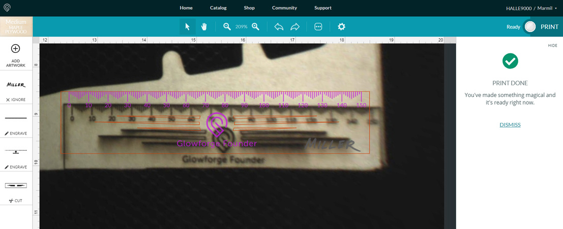
I cut a new ruler, placed in the bottom right of bed. Here’s a screen capture of how it looked in the UI. (Even with me knowing it was going to shift down from where the preview lines were showing, I still didn’t get it right and the bottom edge of the ruler was just off the edge of the material!)
@tony.sausageking I totally agree. This seems like an image mapping problem that should be able to be solved. Seems like we should be able to print out a grid of some sort and place it on the bed and have the camera analyze that and create a correction profile for our machine. I too hope this gets better in the future.
Unfortunately, it looks like your unit is experiencing an issue that we can’t resolve remotely. I want you to have a reliable unit, so I’m recommending we replace this one. I’ll be in touch via email to sort out the details. I’m so sorry about the bad news.
1 Like