Continuing the Discussion

Kind of the similar… power is modulated to match stepper movement, but is slightly off.

, but even that makes little sense, because the horizontal speed and power are identical in every test engrave (in this case, 1000/FULL) so there is no reason it wouldn’t appear in every sample.

1 Like

Very small deviations on the Y steps that the carriage moves for each engrave pass can certainly introduce banding. Here’s another thought: The laserbeam points downward based on the postion of the carriage. If the wheels and rails are not in good condition the carriage would tilt very subtley, causing the beam to strike a little too high or low in the Y direction. The beam is pointed at the target like a gun, and if the aim is deflected just a bit off of vertical it can “miss the target” for that engrave pass.
If a high LPIvalue is being used this could equal double or missed passes. I think that the condition of the wheels and rails could be a major factor…

2 Likes

I think eflyguy is close with his suggestion of wave interference. I do not think it is the laser, I thing it is interference between drive step size and the LPI setting.

My suspicion/theory: Banding is a result of the wave interference pattern between the LPI requested for an engrave and the “natural” frequency of the drive which is driven by the size of the pulley and the resolution of the stepper motors. The forge’s smallest motion increment is finite. One could consider this the “native LPI” of the machine. Banding is what we have is the result when the native LPI and the requested LPI frequencies do not mesh well.

On top of that micro stepping is inherently inconsistent with stepper motors so some error gets tossed in because not all steps are the same size. I believe this is less of a factor in what we see as banding.

Details: For a given motor, there are 200 or 400 steps per revolution to play with at maximum torque for given stepper motor. To get finer motion, one would use micro stepping, which can divide step resolution by a binary-esque value (2,4,8,16,32,64,128,256) [but with a loss of torque] and of lower speeds. (https://www.micromo.com/technical-library/stepper-motor-tutorials/microstepping-myths-and-realities).

The Forge designers had to make some trade-off on the design between torque, speed, and step size in their stepper drive design. I have no idea what they picked so I will not do the math.

Even with small step sizes, we end up with discrete motor steps at the end of the process. These steps combined with the radius of the drive pulley/gear give us the smallest increment of movement the drive can offer. ( i.e. a native LPI maximum) The forge can move in multiples of this step but positions in between are not possible. I think we get banding when the design asks the machine to move to a location that is between stops and the machine rounds up or down to the one it can reach. Classic wave interference pattern is the result. Or in more simple terms, this results in the potential for passes to be unevenly spaced. When the “frequency” of the drive and the “frequency” of the engrave resolution, do not perfectly align we get uneven spacing of the engraving passes as the machine rounds up or down to the closest position it can manage.

This uneven spacing in engrave passes is what we see as banding. This is less noticeable at low LPI settings as even though the lines are not evenly spaced, the rounding error is small relative to the distance between passes so they look relatively even. At higher LPI, the rounding error is much greater as a % of the distance between passes and we see banding as some passes are closer together than others. Crude Example: if the machine native LPI is as shown in red and the requested LIP is as shown in green, then the resulting output will be what is shown in the black. 11 passes as requested but not evenly spaced.
banding 2

If my thesis is correct, then the simple solution would be to only offer LPI settings that are based on (i.e. increments of ) the native LPI of the forge. That would only leave the inaccuracies inherent in microstepping as a source of error which I assume are not huge.
3 Likes

From my understanding this is a cooling issue. Id have to see the entire engrave, but generally this is said to occur when the tube passes a certain temperature threshold causing some slight power loss due to mirror expansion/wave cancellation. It can usually be seen when transitioning from lines that have a smaller amount of engraving to a larger amount of engraving per line.

Again, Id have to see the full engrave to determine if this is what is happening here (according to the research ive seen). If anyone else has any additional examples from this particular unit showing the full engrave id love to see them.

1 Like

PG acrylic, 1000/FULL. LPI as notated. Engraved rotated 90º from displayed.

2 Likes

This seems to be a different situation than the one presented in the images on the other thread. Glowforge uses non-standard scan gaps, and might be introducing some sort of interference pattern in its own rendering process due to this. I think your post goes into it a bit above.

The other images however, Im fairly certain, are due to something completely different (cooling issues), as the banding isnt consistent throughout the piece, only where engraving is most dense.

You have however, reinforced my decision that the 340LPI I usually use is definitely the way to go =)

3 Likes

Thanks for the input, this discussion is exactly what I was after.

As a newb, I was already bummed that they get closed without resolution. But now as someone with an issue, having my support thread closed without resolution is not a great feeling.

It was also a surprise to learn that they don’t have these spare parts on hand. According to support, they’re still trying to find a carriage plate to send to me. That seems like a pretty essential part to have in stock for replacement.

Here is an article I reposted a number of years ago. (Im glad I did, the original lost its images!). It goes pretty in depth in explaining cooling issues in CO2 lasers:

Here is an article on scan gaps that is just an interesting read, and maybe semi-related to the issues @eflyguy found:

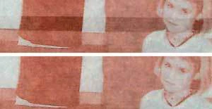
This image (from the first article) shows the same types of banding that is occurring in the images from the other thread:

image

The pattern to look for in determining whether this is the issue or not, is the presence of engraving errors in direct proximity to changes in horizontal engraving load. You can see in this image where there is a large amount of distortion directly adjacent to a large change in engraving load.

Im not sure whether support will ever expand on this or how many people have experienced it, but I definitely know I did on my pre-release machine. Ive been lucky to only see this very very slightly on my forever machine, (except sometimes when I do an engrave first thing before the machine warms up).

3 Likes

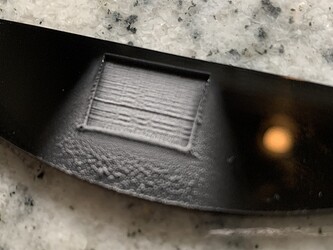
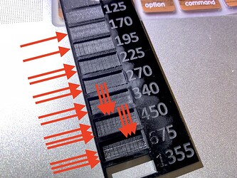
Data. PG Black Acrylic, vector rectangle 16x14mm, SD Engrave (1000/FULL/270lpi)

Clearly shows both horizontal and vertical banding.

Straight off the machine:

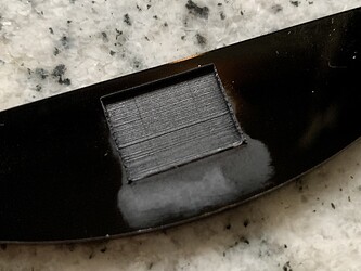
Left 2/3 only “cleaned” with Purell hand sanitizer (70% ethyl alcohol), a blob wiped on with finger, left for about 5 seconds, then brushed away from non-“cleaned” side with soft bristle toothbrush. Rinsed with water spray from right side. NO sanitizer contacted the right 1/3.

Also - I had left blobs of Purell, Germ-X, Equate and Amazon sanitizer on this same sheet for 15 minutes yesterday. None of them left any mark.

It’s not the alcohol leaving marks on our engraves, but it does make them worse.

3 Likes

OMG. I love your new avatar! I also admire your restraint… Internet Tough Guy. :rofl:

In defense of the OP, any online response is open to interpretation. I didn’t see any trolling, you just speak as a matter of fact. They don’t know you. That can easily be taken wrong, especially if one is in a defensive position.

Me - I’m likely to chase down someone who flipped me off with the intention of feeding them that finger. In my defense I do have Scottish/Irish descent which presents that particular characteristic.
It’s also a good way to get shot.

3 Likes

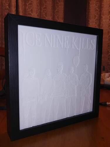
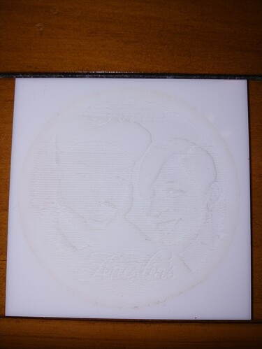
Apologies for not joining in on this sooner, as the OP of the original thread I can tell you the banding was even across the X axis but it came and went sporadically on the Y. I no longer have the product as it was signed by the band (Ice Nine Kills) and then auctioned off to benefit cancer ( it sold for $350 ) . I used a tool to make the bands as light as I could. I do have a couple of photos of before I put the reflective backing in, so pardon the “hot spots” with the light…

the final product looked much better, and even better in person.

Hope that helps

6 Likes

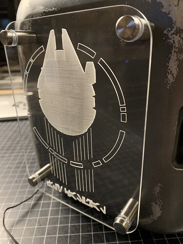
Just saw this image pop up on the forum. You can see where it finally finishes engraving the cockpit that the thermal issues seem to subside. Very clear line there.

4 Likes

Did another 3D Engrave tonight, same issues this time I had one real deep line across one part.

… and from that deep line for like 3/4th an inch the etch looked good , then back to banding.

Settings were stock 3D engrave for PG medium white acrylic : Speed 501 ; Vary power / Full power (Pro) ; 340 LPI ; 1 pass

I am cutting it again to see if it repeats in the same places or if it comes out different.

1 Like

Ok so I cut it again, and no deep line across the forehead or anywhere. I made sure to only move the print over and not up or down. It appears to be random where the striations appear and how long they last. This would suggest that the assumption about it being tied to power or temperature of the tube may be correct. Next question is how to fix it or work around… also should I open a new thread? if so they just going to slam it shut on me again? I just want to be assured they are looking into this.

1 Like

Open a new thread and share both results. They typically say that when they close a thread - post again if the problem re-occurs.

Also, if this is PG material, they may reimburse you for the ones that are ruined.

1 Like

Was the last engrave shown above the first engrave you did after powering up the machine? Also, what would you guess the temperature was in the room when you did this engrave? Is this a pro or basic/plus?

1 Like

the three photos are all the same engrave, after powering up the machine. The room is around 72f / 22c - It is a Refurbished Pro, my first machine had issues cutting all the way through. Oddly I don’t think I had this issue (this bad) with the original machine.

I ran another test cut where I lowered the max power to 50 and the speed to 220, left it at 340LPI and single pass. The time went from 24 minutes to an hour. The cut came out better, still some striations, no where near as bad though. However the depth of cut was not entirely enough so I am testing now with more LPI to see if that helps :slight_smile:

Well I was wondering if any of the ones you had a problem with were a first engrave since the machine had been off a while. That can cause issues sometimes while the tube is changing temp from ambient to operating temp. Sometimes second engraves come out cleaner

2 Likes

This topic was automatically closed 32 days after the last reply. New replies are no longer allowed.