Could really use an expert's input on a Fusion 360 question? 😄

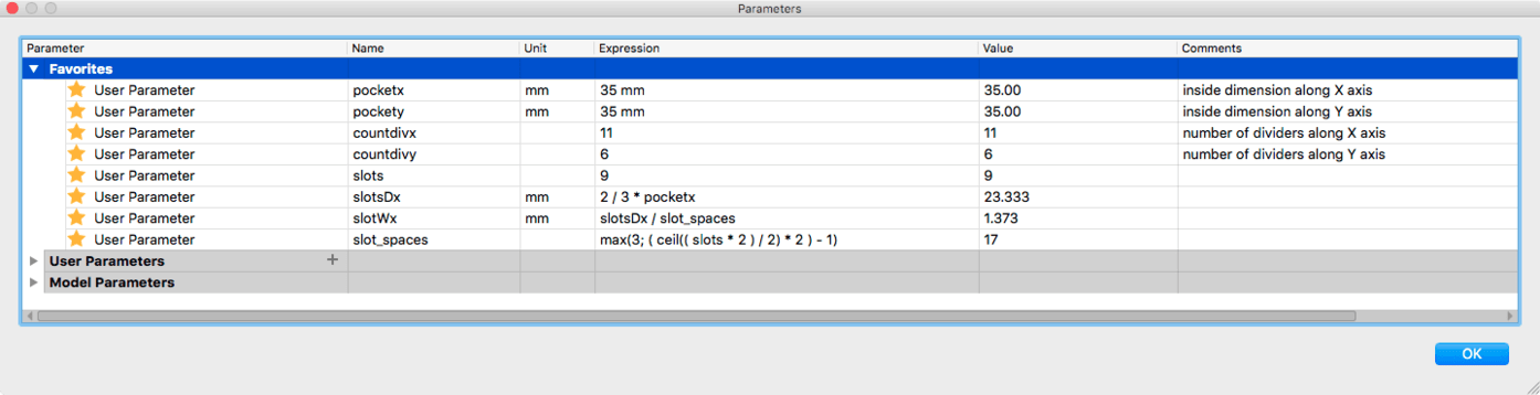
I’ve been playing a little bit with parametrics in F360, and I created a simple divided tray design, that I want to be completely parametric.

(I’ve got a handful of variables created for it, and the idea is, I can go in and change any one of them and the whole design updates.)

This is what i’m running into with the design:

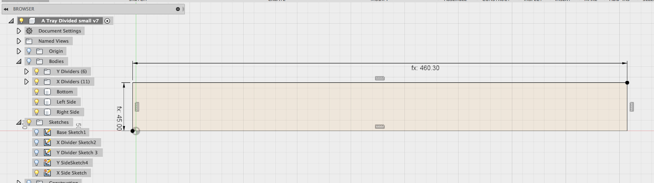
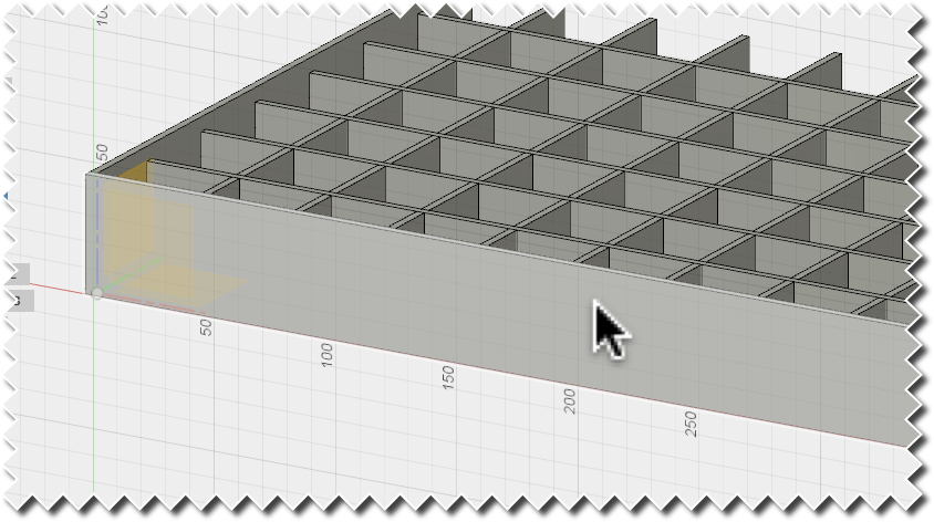
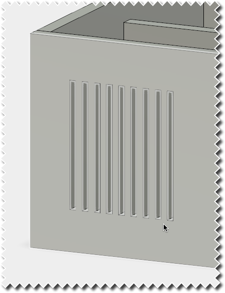
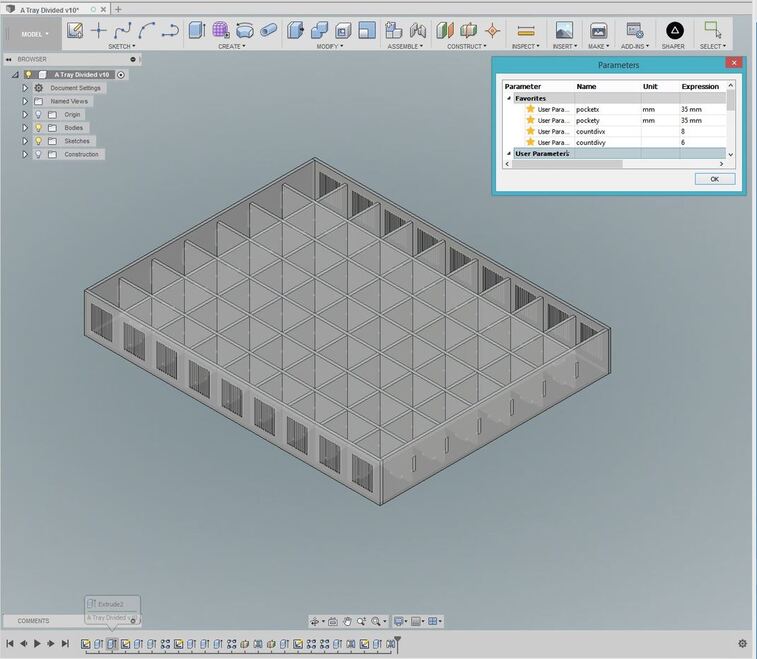
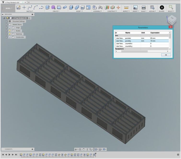
It starts out looking like this:

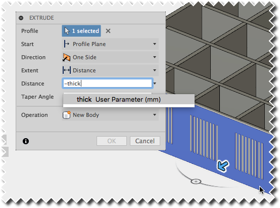
Everything looks hunky-dory and the rectangular patterns being populated in the sketches are correctly being subtracted from the extrusion for the front, side, and base. (Which are then mirrored, so we just have to deal with one instance in each case.)

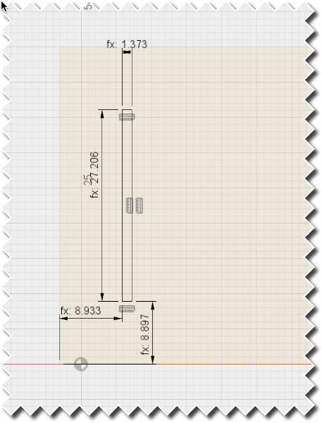
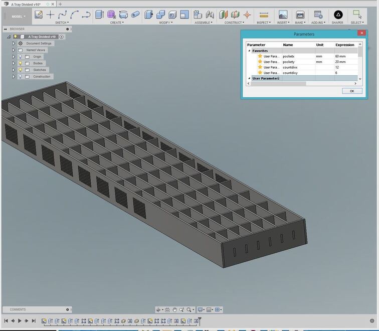
I can change the size of the slots, or reduce the divider count, and everything tracks without issue:

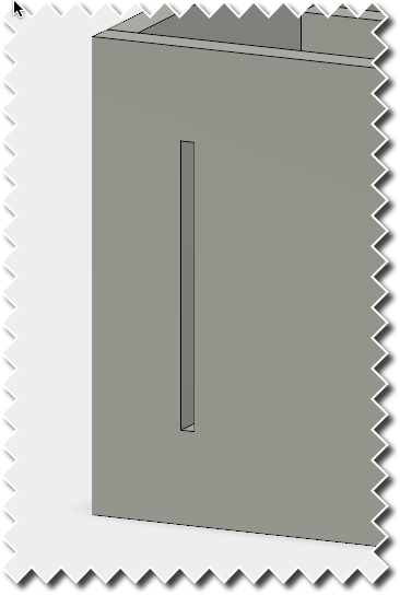
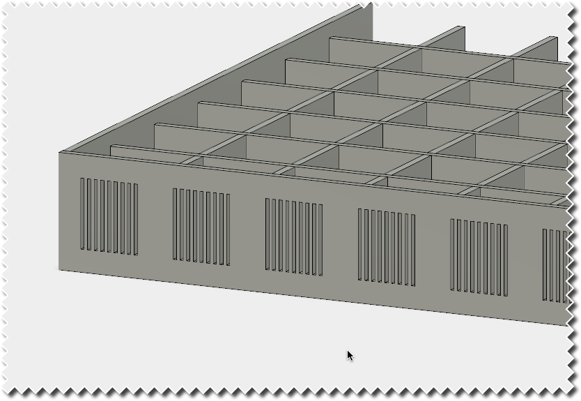
But here’s what’s happening when I increase the divider count on either the X or Y axis, above what it was initially. (More on that later, it’s not absolute.)

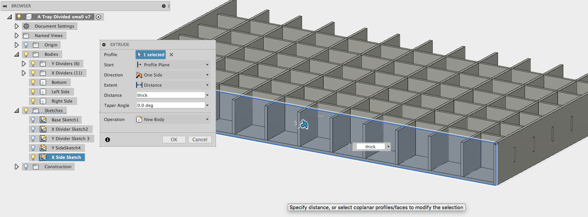
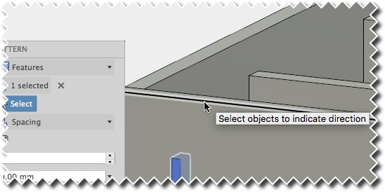
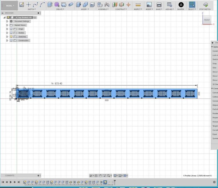
What I don’t understand is why the effects are not being picked up on the extruded body (the front) even though they are already rendered in the sketch for it in the timeline:

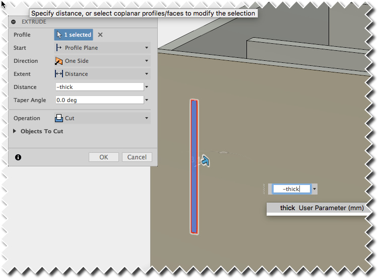
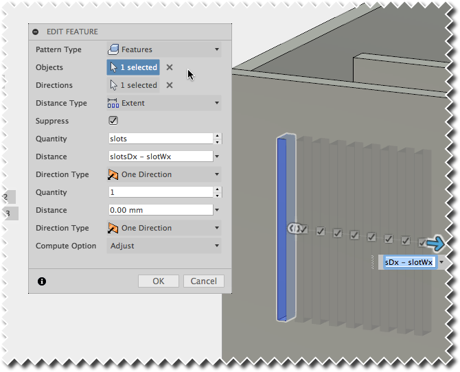
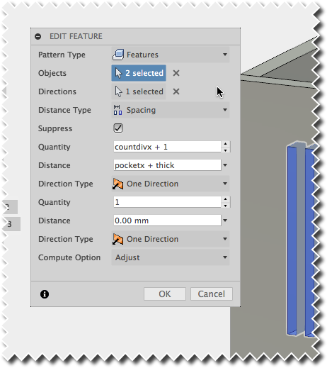
If you go in to edit the appropriate extrusion for the body, you’ll see that the number of selected objects for extrusion has increased from the originally selected 2, to a ridiculously high amount like 247 as shown below.

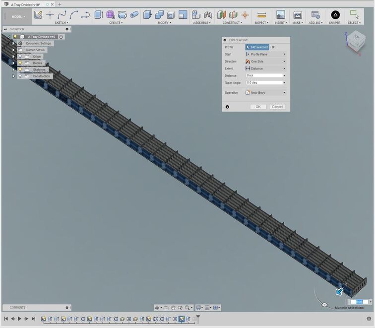
It appears to me that anything new added to the sketch is being captured for extrusion by default, when the object in this case is to just extrude the items originally selected? The sketch is correctly populated, and it can be used to export to DXF for laser cutting, but it precludes using any of the face capturing plug-ins, which can be handy if you want to apply a kerf adjustment on one or more individual parts, but not the whole thing.

So anyway…it’s not a major issue, since I did figure out a way around it. Once you set the divider count to a ridiculously high number and edit the extrusions for the extra-large size, you can then lower the count, or raise it again to any number less than or equal to that original max count number, and everything tracks the way it’s supposed to. In this case, setting each divider count to 30, (total of 961 pockets available) worked fine. (Higher than that was taking too long to process.)

I know there’s probably an easier way to do this, and I am a bit hesitant to let experts into the file,(gonna laugh their asses off), but if anyone wants to tear it apart to see what I did wrong, I saved the original file that retained the problem. You can PM me your email address and I’ll give you access to it.

And many thanks for the assistance! :grinning:

2 Likes

Fusion 360 is on my list to learn … wish I had something to contribute here!

2 Likes

If I understand your problem, it is because you’re relying on sketches for the pattern :slightly_smiling_face:

That’s precisely what I learned not to do with the finger-jointed boxes I created.

Since you want this to be parametric, instead of just building a single version, you need to rely on features and faces for your patterns.

Now that I’ve finished conference calls for the day, I’ll try to take some screenshots for you.

3 Likes

I did try it first with the faces, that didn’t work out either, but maybe I was doing something incorrectly when selecting them. (The faces method worked fine on the tote, but not this one.)

If you want to send me your email I’ll give you access to the file so you can poke around in it. (Or maybe I can just save a copy to desktop and forward it to you if you don’t want to give out your email addy…let me do that, I’ll PM you with the file.)

It’s a lot of fun, you should give it a try. (I’m still a baby with it myself, but there have been a lot of really outstanding tutorials from the members here that really help…check out the Matrix…it’ll get you going in no time!) :grinning:

1 Like

Do you have any manual steps in there? I.e. select and extrude? If so, that’s deadly to parametric modeling.

I’ve been down this path and have not succeeded yet. It is a giant, tedious, pain to do. Especially if you try to add kerf into the mix.

2 Likes

Yeah, some extrudes. Might have figured out a way around it, but it’s not optimal. :neutral_face:

Also try the fusion 360 forum:
https://forums.autodesk.com/t5/fusion-360-design-validate/bd-p/124

2 Likes

I will if no one here knows the correct method. (Really hate to look like an idiot in front of people I don’t know though.)

I’d much rather look like an idiot in front of people who do know me…they’ve come to expect it. :smile:

(And I’ll run it past @Secret_Sauce first.)

2 Likes

Extrudes are OK, but it needs to be an extrude that didn’t involve, say, shift-clicking to select multiple regions.

I.e. if you want variable # of tabs, you need to model the tabs as a repeated operation of some sort that produces a single polygon for extrusion.

As I said, huge pain. I’ve tried several times and almost got it, but one wrong or missing constraint will ruin your whole design.

3 Likes

Yep, some of that involved. :face_with_raised_eyebrow:

I went to look and saw that Autodesk had it and it was based on a monthly fee.

Blender has a variation of this that is probably more powerful as it is very multidimensional bit also very difficult to wrap your head around for that reason.

Learning a program like Inkscape is like climbing a mountain but Blender continues to feel like Lewis & Clark climbing the first mountain and expecting to see the Pacific just beyond.

I can manage well with what I know but not even started climbing the mountains beyond.

1 Like

If you are a hobbyist or a small company (I believe under $100k in revenue), the license for F360 is free, but must be re-registered annually.

2 Likes

@Jules, here are the instructions for how I fixed part of your file. I hope this makes sense, as I didn’t have enough time to write up detailed reasons for why you do each step. I’ll try to create a video version of this tomorrow.

Step 1. Setup parameters to make the number of slots along the face parametric

Existing Parameters

pocketxUser defined: the inside dimension of each pocket along the X axis
pocketyUser defined: the inside dimension of each pocket along the Y axis
countdivxUser defined: the number of dividers along the X axis
countdivyUser defined: the number of dividers along the Y axis
thickUser defined: thickness of the material being used
heightdivCalculated: the height of the dividers
heightsidesUser defined: the height dimension of the box’s outside walls

New Parameters

slots - User defined: the number of slots in each group along the face
slotsDx - Calculated: the distance covered by each group of slots along the X axis face
slotsWx - Calculated: the width of each slot
slot_spaces - Calculated: the number of equally sized spaces within each slot group

slot_spaces must always be an odd number (either an even number of slots with an odd number of spaces in between or an odd number of slots with an even number of spaces in between), and we always want at least 3 here, since the bare minimum is 2 slots and a space in between.```

Step 2. Create a sketch for the X axis wall

Set the dimensions for the height and length of the wall.

Step 3. Extrude the wall

Use the thick parameter to extrude the profile that was created on the sketch in Step 2.

Step 4. Create a new sketch

Select the option to create a new sketch from the toolbar (if you have a shortcut), or from the Sketch menu.

Create%20Sketch

Select the face of the wall extruded in Step 3.

  1. Create a rectangle on the sketch.
  2. Set the dimension for the height of the rectangle: 6/8 * heightdiv
  3. Set the dimension for the width of the rectangle: slotWx
  4. Set the dimension to define the offset from the left edge of the sketch: pocketx / 6 + thick
  5. Set the dimension to define the offset from the bottom edge of the sketch: ( heightsides - 3 * heightdiv / 4 ) / 2
  6. Stop the sketch

Step 5. Extrude a cut to create the slot

  1. Press E to Extrude
  2. Select the profile of the rectangle that you drew on the sketch in Step 4
  3. Enter thick as the distance (use a negative number if the arrow is pointing away from the face to make it change directions)

You should now have your first slot in the face.

Step 6. Create the group of slots

  1. Create a rectangular pattern from the toolbar or from the Create menu.

Rectangular%20Pattern

  1. In the dialog that comes up, set the Pattern Type to Features
  2. Click on the Select box next to Objects

Rectangular%20Pattern%20Top

  1. Select the feature from the timeline, which should be the latest object on the timeline

Select%20Feature

  1. Click on the Select box next to Directions
    Rectangular%20Pattern%20dialog%20-%20Direction

  2. Click along the edge of the face where you are adding the pattern (or the axis from the origin point that is along the direction you want to create the pattern) – in a more complex model, it is important to not select an edge that might disappear when you change parameters

Select%20Edge

  1. Set Distance Type to Extent
  2. Set the Quantity to slots
  3. Set the Distance to slotsDx - slotWx – you need to remove the width of the first slot that you cut from the distance you want to cover

Now you have the first group of slots cut in your wall face

Step 7. Replicate the group of slots across the face

For this pattern, you want to duplicate the extruded cut from Step 5 and the rectangular pattern from Step 6. Select the option for Rectangular Pattern from the Create menu again.

  1. Again, use a Pattern Type of Features
  2. Select the extrusion feature and the rectangular pattern feature previously created from the timeline

Select%20Pattern%20Objects

  1. Select the direction that you want to replicate the pattern
  2. Set the distance type to spacing, since we know exactly how far apart these patterns should be
  3. Set the quantity to countdivx+1 – because we have 1 more pocket than we do dividers
  4. Set the distance to pocketx + thick – because each pocket is a specific width along the x axis, but we also need to include the thickness of each divider between the pockets

Now you have all of the slots along the face.

Step 8. Duplicate the face to the other side of the box

  1. Press E to Extrude a profile
  2. Select the face of the wall you just created and placed the slots in

Extrude%20second%20wall

  1. Set the Start to Offset Plane
  2. Set the Offset to -gridlDy - thick to start the new extrusion at the other side of the box (if you selected the inside face of the wall in #2, then the Offset would be girdlDy
  3. Enter thick as the distance if the arrow points toward the face, enter -thick if the arrow points away from it (to switch direction)
  4. Set the operation to New Body
  5. Click OK

Now you have 2 walls with slots that will dynamically change depending on the number of slots you define, and the size of the pockets.

You would need to create an equivalent parameter for slotDy and slotWy along the Y axis to add slots to those walls, and you would use pockety, gridlDx and countdivy to replace their X axis equivalents in the previous step.

11 Likes

I should mention that I think I made a mistake in the slot_spaces formula in the file I sent back to you. The one in the image above is correct.

Pardon my french but “holy :poop:!”

Thanks ever so much, that was about a world more than I was expecting!
I’ll be honest with you, I never would have wandered down that path.

Now forgive me while I study this intently…I had looked at the file you sent and got rapidly lost.
(You really are an expert!)
:grinning::tada::confetti_ball::balloon::boom::dizzy:

3 Likes

Not even close; I’ve just made so many mistakes in my files that I’ve spent a lot of time trying to figure out how to best leverage patterns and simplify sketches :smile:

Each design teaches me something new–after I completely screw it up at least 3 or 10 times. :rage:

4 Likes

Oh, yeah, I’m easily up to ten on this one! :smile:

1 Like

Looks like @jbpa got to this before I could. Glad you got it working. I do have a few other ideas on how to make your file work more efficiently. I’ll make you a video. If I can’t do it over the weekend, I’ll surely do it on Monday.

5 Likes

Excellent writeup!

[wrong]Another option someone might elect to take is to add the slots to the X Side Sketch and then pattern them within the sketch. (do all this between step 2 and step 3) Then when you extrude the wall in step 3, you would only need to select one profile (no Ctrl+click selections required) so it will extrude.[/wrong]

This method has a slight advantage in that it doesn’t add another feature to the timeline, but has a disadvantage in that it wouldn’t be compatible for shapes completely inside other shapes (like the holes in "O"s, if you were doing embossed lettering or something). (and a big disadvantage in that it doesn’t actually work)

3 Likes