I’ve been messing around with setting up a capacitive touch control panel for my electric car project for quite a while and now that the GF has arrived I get to build some better true-to-life mock-ups to test out.
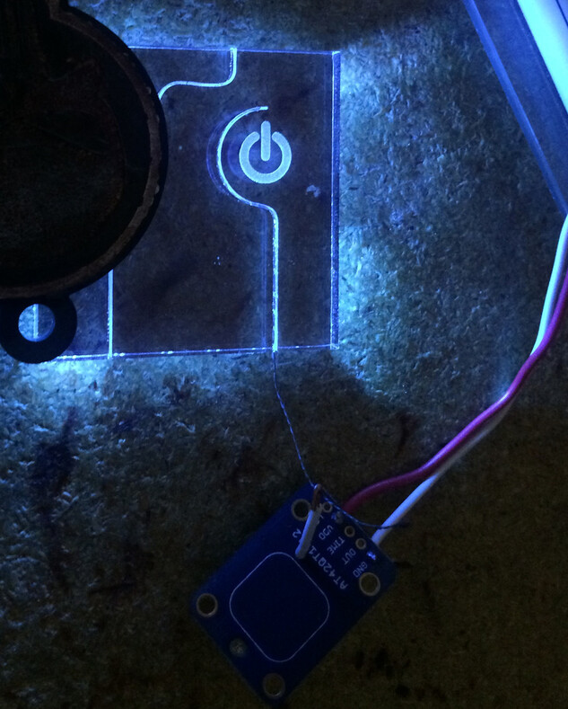
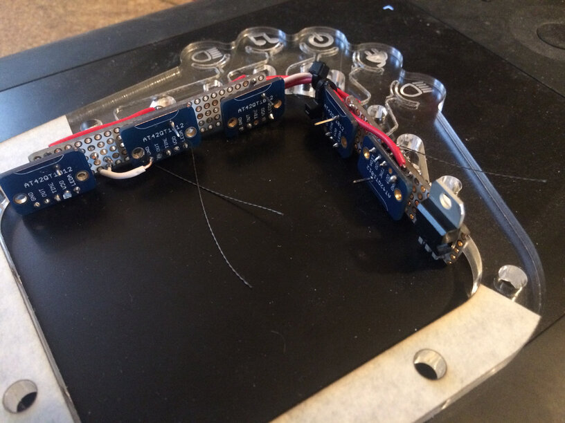
The blue PCB is a capacitive touch sensor breakout from adafruit.com
The acrylic is just a 2" square not anything remotely like the actual design, but the engraving and score patterns are for helping me test the functionality of the circuit itself because the capacitive touch is sensitive to wire lengths, wire diameter, distance from the surface of the touch pad, etc.
I used the glowforge to cut a score into the acrylic about halfway through the thickness (Thick PG Clear) and turns out the thread fits perfectly into the score using the tip of an X-acto blade to help seat it into place (the score is too narrow to use sewing pins for that!)
The semi-circular curve at the end of the score helps to increase and target sensitivity for the touch pad at that area. I might make it a more complete loop at the end but right now I prefer the aesthetic of this open curve.
Of course a nice blue LED just sets it off like mad. I love the way the scores look when lit!
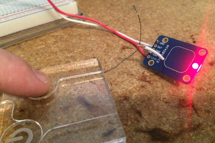
I think of it as a clever redesign of the classic game Operation. You touch the metal around the hole and the light and buzzer sound. Just a lot less pixies running through these wires and such that skin surface can trigger the current. At least, that’s in my mind.
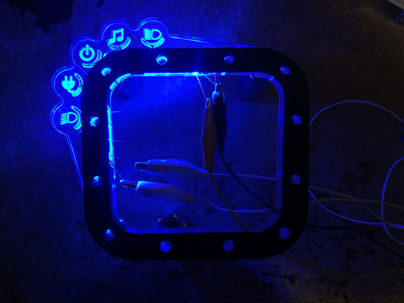
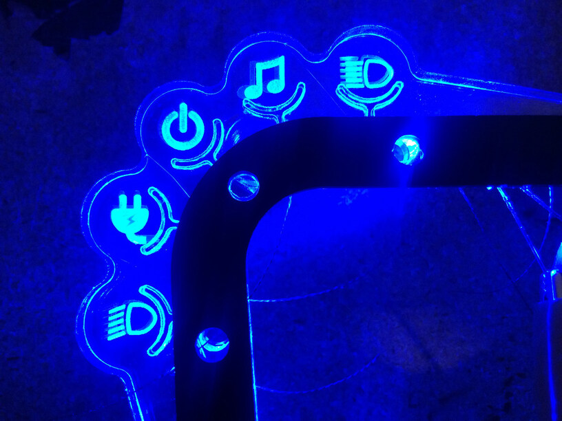
Yeah… I’m gonna need to tone down the brightness of these LED’s a little bit.
I decided to make the touch pads into half moon shapes so I ran those scores on the glowforge then used CA glue to bond the conductive threads into the scores. This shape gives a nice responsive feel to the touch sensor.
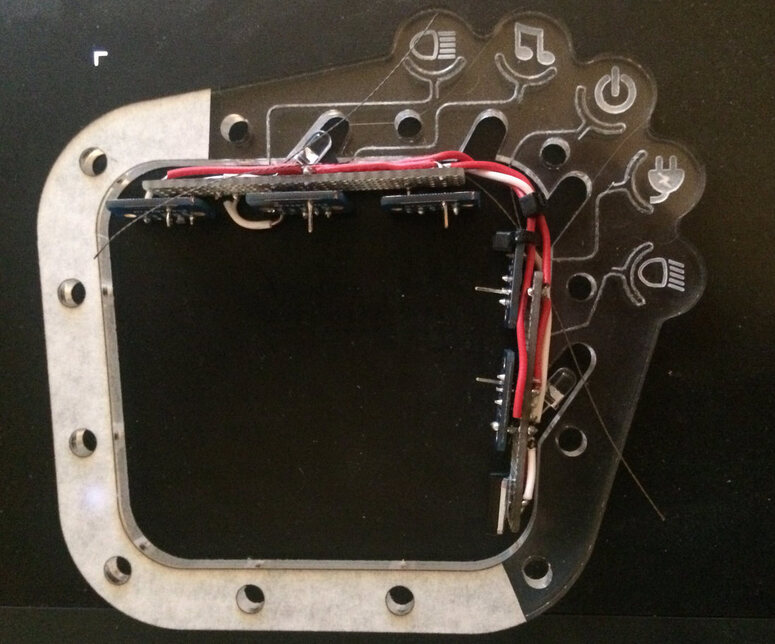
You’ll notice there seems to be a double image of the engraved parts and that’s because there is. The previous version of the clear acrylic part is underneath, its only purpose now for helping to hold the LED’s in place to take this photo.
Tomorrow I get to work wiring up the capacitive sensors, but I tested each one as I got the conductive threads set into the acrylic and they all work well. Now the test is whether they all work well together simultaneously, or if they crosstalk each other.
I’ve only turned on the Glowforge once today for about 10 minutes, just to run one part for this project. Have spent the majority of the day building the circuits for the capacitive touch part, but it’s turning out fantastic so far. Need to test and see if it works but I’m at that point where I’m tired of looking at it for the day. Maybe my obsessive behavior will kick in again once I take a little break.
These photos really show the scores that were lasered into the acrylic, and how I had actually built recesses into the acrylic design for the LED’s to nest into. I had planned to use 4 LED’s to help make the lighting even but turns out that was not a problem at all, and even two LED’s running at full brightness are too much. Now that I have circuit boards built instead of using alligator clips, the LED’s are wired in series so they split the voltage and tone down the brightness to a nice level.
So the little blue PCB’s in the photos below are the same PCB as the sensor in the first photo I posted above. I just cut that PCB apart to save some size. Luckily that chunk I cut off is just an integrate touch pad and these still work OK without it. (Don’t worry, these boards are only $5 each, worth the risk to find out if they can be hacked in half hahaha)
Also, if you hadn’t seen, Adafruit does have a 5-pad (and even a 12-pad) capacitive touch board. Would save you from cutting lots of boards in half (the 5-pad is also only $7.50 – https://www.adafruit.com/product/1362 )
I love the idea and your design is looking great, but have you considered what happens if you get a “touch” detected at the worst possible time? I’m not suggesting you don’t do it as long as it has been considered. Good luck with the car.


 (the 5-pad is also only $7.50 –