Now that I’m switching to a capacitive sensor that has 5 inputs instead of using multiple single sensors as in the above photos, that’s less of an issue. The sensor only detects one touch at a time so you don’t have an accidental touch while trying to press one of the other buttons.
The sensor also calibrates itself when powered up, so it will basically take readings from its environment and it says to itself “OK, that is the base level amount of noise in the area” so now it only detects larger changes.
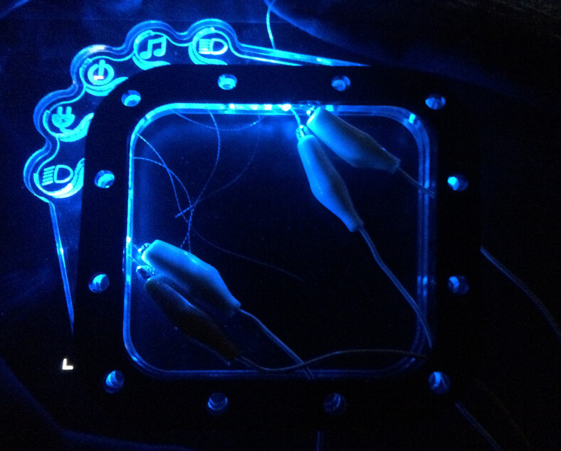
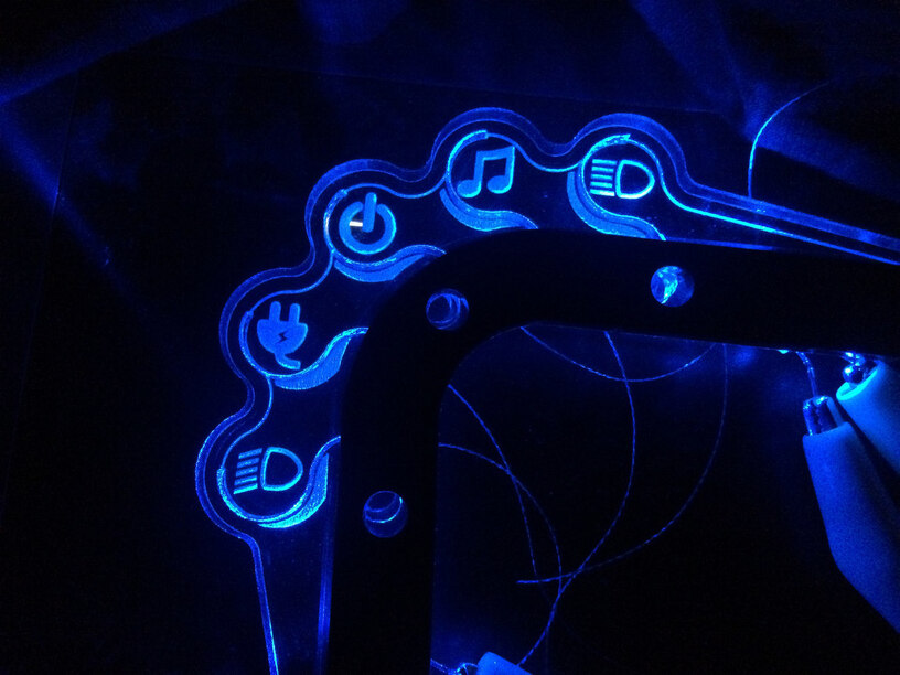
Plus, the only critical function in this control set is the headlight on/off (lower most icon). The Plug icon is for putting the car into battery charge mode, which locks out throttle input so the car will just turn off. The power button is Drive mode so worst case again, the car turns off. The musical note is for turning on the stereo without activating other accessories, turning that on or off while driving won’t have any impact. The headlight icon at the top is just the high beam on/off.
And if all else fails… Being an electric car, and the fact that the new 5-pad sensor will be interfaced to the car through an Arduino Feather, I can tap the throttle control into the Arduino and program it to lock out any commands from the capacitive touch if it senses any throttle input. Dang that is cool!
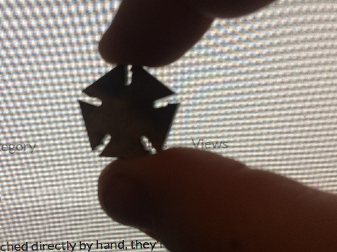
Update! The new 5-pad capacitive sensor is either a bit less sensitive or I didnt have one of the thin wires set deeply enough into the acrylic so I went ahead and ran another acrylic piece with a wider score that would be easier to set the wire into. I havent had a chance to test the sensor yet but now the wires are set halfway down into 1/4" material instead of just about 1/16" deep as in the first one. I engraved/scored the back side of the acrylic so this brings the wires closer to the touch surface thus increasing sensitivity.
I completely redesigned the artwork while I was at it. Second verse, better than the first!
Yeah that’s been a problem the last 6 years I’ve been building this car. Every update is basically just some other new component or part I’ve made, and without context to how it fits with the rest of the car none of it makes any sense.
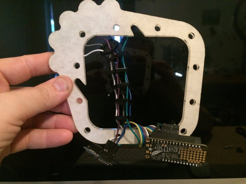
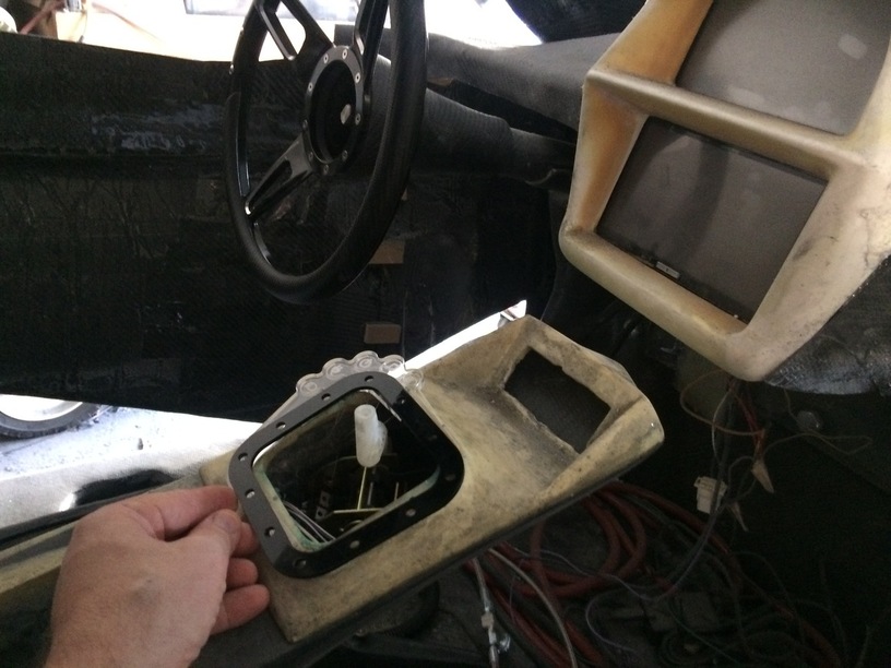
So this is the center console. The throttle control is hand-operated and goes right there in the console. Cosmetically it’s like a shifter lever, except it’s the throttle. There will be a boot to close off the space and this acrylic bit above is the trim ring that will secure the bottom of the boot to the console.
The dashboard has two screens and other than that, no other controls at the moment because there isnt anything else that needs controlling, for now.
Ohhhh that’s just one of the fantastic opportunities you’re afforded when you miscalculate your original plan.
I think the actual problem is that I’m now 60-70lbs heavier and thus further forward in the seat, than I was 5 years ago when I set the seat positions. That seems to have impacted roof height too… so I can compensate for one while messing up the other. LOL. So, yeah I’m on a diet now.
Plus, pedals are normal. I have one pedal to operate the front hydraulic brakes but for the most part, braking and reverse are built into the hand-throttle as well. Pulling back while moving forward applies regenerative braking, pulling back while stopped puts it in reverse. There is a deadband safety interlock that must be met before switching from brake to reverse will be allowed.
Hehe, when I replaced the original foam in the driver’s seat in my 50 year old Mustang it jacked my arse up 3 inches. Now I look through the blue tinted band at the top of the windshield.
Nice work on that ride man! Great how the laser is allowing a deep level of customization!
I’ve given workshops making music controllers using the “electric paint” from Bare Conductive, their Touch Board, and copper tape, as well as just the paint with plain old Arduinos. With that you can make pretty much any MIDI controller you want. What @mpipes is doing with the acrylic opens even more opportunities!
https://www.bareconductive.com if you haven’t seen it before. They even have some tutorials on making MIDI controlled things.
I remember using one way back in the 1990s when I managed a small chain of music stores. It was pretty neat back then. I bet they’ve only gotten more nuanced since then.
In between testing other stuff like engraving bevels, dovetail joints, etc. I have been going through iterations of this capacitive touch control. Kept having issues where some “buttons” would work and others wouldn’t. Reboot the sensor and different buttons worked and others did not. Touch the lead wires directly instead of touching the acrylic pad and they all worked well! Based on that I kept believing I just did not have the channels in the back of the acrylic cut deep enough so I ended up running test pieces and samples that would work fine. Then when I ran another iteration based on those working samples I’d get it all together and NADA!!
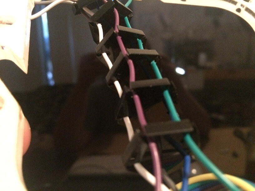
Turns out the culprit was not the acrylic part nor the sensor, but it was the lead wires themselves. Even though they worked fine when touched directly by hand, they’re breadboard prototyping wires which are made in flat ribbons and joined together parallel to each other. That’s a worst case scenario for picking up noise and I should have known better, but because they did work, it threw me.
So, I can’t have a mess of unruly wire hanging out here but I can’t bundle these wires together because it just won’t work.
Ah-HAH!! I used the glowforge to make spacers that the wires snap into! These actually have a little nodule inside the channels that the wire positively locks into and stays put! And when I say little, I mean literally fractions of a millimeter. It’s amazing the detail we can cut with this machine!


 I have one pedal to operate the front hydraulic brakes but for the most part, braking and reverse are built into the hand-throttle as well. Pulling back while moving forward applies regenerative braking, pulling back while stopped puts it in reverse. There is a deadband safety interlock that must be met before switching from brake to reverse will be allowed.