sweet!
5 Likes
So much talent in one family! I think we are gonna see some pretty cool collaborations from the two of you.
3 Likes
Ha! Fantastic!! Love the sketch and the print.
2 Likes
… and 7 minutes later … you are going to have so much fun, enjoy!
8 Likes
Wow! The engrave on that looks like puddling on a weld. Nice effect, and by the gloss on the edge it looks to have been melted.
Thanks for the material demo!
1 Like
Looks even cooler under a microscope. Those are some pretty tight (straight) raster lines.
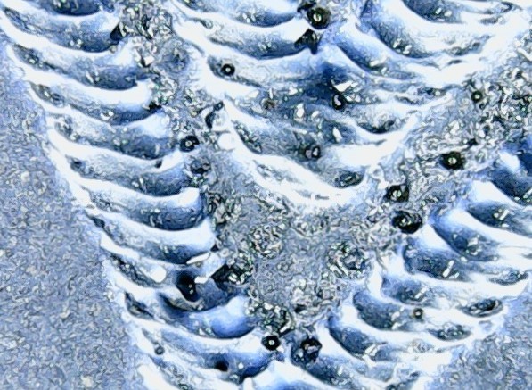
Looking at where the W an V come together.
39 Likes
Yes it does!
3 Likes
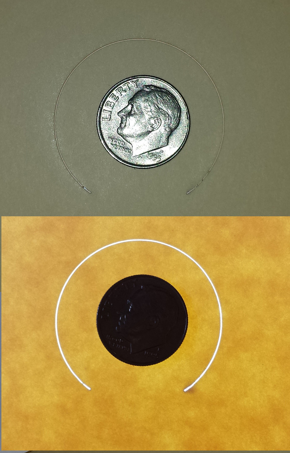
Did a quick look at the kerf width. Took a thick manila file folder and cut part of a circle. The first pic is with a dime for size reference and the bottom pic is the same on a light table to better see the cut.
22 Likes
I think Dan has said the lid is a UV filter.
Looks a lot wider than the 0.008" quoted for spot size.
Might have to account for the spread of light through the crack. It’s an optical illusion. No way for me to actually measure the kerf. And of course spot size is not kerf.
3 Likes
If you have a digital caliper you can measure the difference between something you have cut out and the hole left in the material and divide by two.
2 Likes
I wouldn’t try that on a circle. Would never be able to ensure I was measuring the widest part of the circle. Maybe a square. But not gonna bother with harbor freight calipers.
4 Likes
I did a quick measure on the picture as downloaded. In the top image the dime (diameter 0.705") is 415px and the kerf is 3-5px. In the bottom one, the dime is 412px and the kerf is 6px. So somewhere between about 0.0055 and about 0.011. Maybe. We don’t know the beam profile, so for something thin, kerf could potentially be smaller than spot size, but unless the cut is perfectly regulated and focused, it could be much larger.
I have a Mitutoyo micrometer accurate to 1um and various hole gauges for measuring inside diameters. I also have a micro graticule for microscope calibration, so I am well set up for testing the GF when it arrives.
3 Likes
IMHO, using calipers to measure one cut width is problematic. Much better to take a rectangle of material, make a zillion cuts across it, stack the resulting pieces together and measure, find amount of total shortening and divide by a zillion. That should give a much more accurate estimate of the cut width.
edit: my definition of “zillion” is “a number between 10 and 100” 
6 Likes
Got any feeler gauges for setting spark plug gaps or valve clearance?
If you do they a great way to test the kerf size, although you would need to make a straight cut.
Congrats on the pre-release BTW!
5 Likes
Why is measuring a circle difficult? Especially with something as small as a dime… just measure it like the bottom figure as opposed to the top figure:
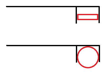
Please forgive me for the crude nature of my MS Paint drawing 
5 Likes
As I recall the kerf quote was a range with .008" being the very bottom of the range. Material, thickness and beam focus all play their role. It wouldn’t hurt to know the kerf today to get an idea of where they are at, but until the software is released there is an asterisk after it. I want to do various inlays and the like, so I’m anxious about it, although based on the precision tools you have I imagine you’re probably more concerned than I am.
Outside diameter is no problem but inside diameter is more difficult.
1 Like
Very true… but if I create a circle of 1" and cut it out on the GF, and I measure the outer diameter of said cut to be .8", then wouldn’t it stand to reason that the inner diameter of the other piece would be 1.2"?
Disclaimer: The numbers in the example above are fictional and are in no way indicative of the actual kerf produced by the GF. I chose them because math is hard, and these numbers make it easy.
5 Likes