First Lamp makes

So I ve had my GF a couple of weeks now and have only made a few things on my own designs.
I just wanted to share my first two designs (lamps) made on my GF.


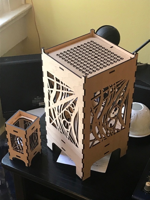
One was a scale prototype, but its a perfect size for a votive candle holder and the other is a full size lamp. They both have different side panel cut out designs. The larger one I intend to make opaque with some handmade mulberry paper, which I have on order, and i’m working on an arduino contoller for some programmable LED lights (Neopixels) for that one
They both came out wonderfully although they taught me a couple of things in the process.
I wanted to describe my workflow as its kind of convoluted and I wanted to hear from anyone else if they have improvements. I guess most of the reason for my workflow is i’m more comfortable with Fusion 360 than Illustrator.
The main design was created in Fusion 360 parametrically modelling the box joints and general shape and created solid components for the side panels and top middle and bottom panels.
I saved this as a master file so I can make lamps of any size and cut out patters from this.
I created the side and top panel art work in Illustrator. I saved these illustrator files as SVGs
I imported the SVG art into Fusion into a copy of the master file.
I extruded cut outs based on the SVG artwork into the solid panel model in fusion for the side and top
I then saved DXF files for all the components in Fusion
It would be great to stop here and just send the DXFs to the GF :slight_smile: (hint hint)
But it doesn’t support DXF files. Also my copy of Adobe Illustrator CS6 also wont import the Fusion 360 DXF
So I have to use Inkscape to open the Fusion DXF files then immediately save them as SVGs
Now the Glowforge Ap will see these and its just a case of positioning and cutting.
So that is all quite long winded… Anybody have better workflows?
I would love to see a plugin for Fusion 360 to just print out from, using the CAM side you can model a water jet or laser… but it wants to send Gcode.
I realize I could do it all in illustrator, but I cant get my head out of parametric modelling.
I also realize I don’t need a solid model of what i’m making… just the lines, so does anyone do anything just with sketches and not bodies?

Things I discovered while printing
The placement calibration is off left to right by a few mm so I cut off the edge of my wood. So one side is shorter than the other (nothing the compound miter saw wont fix) - but how do people maximize the use of the wood if you cant rely on where its going to print in relation to the scan image?
In removing the tape from the sun and moon patter, I broke a few of them as they’re fragile… how do people remove the tape on delicate items?

Thanks
Jerome

35 Likes

I generally try “hey honey, can you come here for a minuet?” and hope for the best :slight_smile:

12 Likes

Wow, that’s an amazing first project! :grinning:

:joy:

4 Likes

So, does she play the minuet while you finish the delicate tape removal … OR, does she come and lend her able assistance for a minute or two?

:glowforge::sunglasses:

6 Likes

After being married as long as we’ve been I’ve been deemed totally incompetent for “gentle” work, so she weeds it. I have a friend at work who is OCD about that stuff too, so I just take her examples of what I’ve cut and she’ll weed everything just to return order to the universe

13 Likes

I add an exterior border line in an unused color that exactly fits around all design elements. In the GFUI, I set everything to Ignore except the border, which I set to a very fast & low power score – just enough to lightly mark the masking without going all the way through. Place, score, adjust (material or design), repeat as needed. Once you have everything the way you want it, without moving the material or the design set the bounding box to ignore and your design to engrave/score/cut as needed.

10 Likes

I like that idea, I’m going to try that… or maybe just some corner dots

:+1: Corner registration marks work well for regular shaped materials.

1 Like

Beautifully elegant

1 Like

Lamp and mini-lamp make quite a statement! I’m looking foward to seeing the final version with your handmade paper.

3 Likes

They look great! Looking forward to your next project!

1 Like

There is, in theory, a CAM postprocessor for Glowforge, but I have never gotten it to work, and I think others here have also reported lack of success. I’m not sure how much sense it makes, since it’s not generating G-code, just SVG, and you might as well do that with either the existing DXF/kerf correction plugin or the new one from Shaper Origin.

I’ve had similar questions about this workflow, specifically around parts that combine traditional CAD drawing with “artwork”. It seems like importing designs for cuts and engraves into Fusion 360 only to send them back out adds a few layers of difficulty versus doing the overall geometry in F360 and then adding cosmetic elements in Illustrator or Inkscape. But that gives me philosophical problems, since part of the value of modeling it in F360 is to see my finished design in 3D, as well as the practical problem of how to handle changes. CAD is great for making things parametric and being able to make an adjustment that propagates through the model. It would suck to repeatedly do that and then have to reapply all of the artwork in one of those non-parametric drawing programs. I’m kind of curious how this is handled in industry.

3 Likes

There is a way using a CAM processor, but I don’t recommend it. The output is not as nice as the DXF->Inkscape->SVG route. Although I have found an Inkscape bug where certain arcs appear on the wrong side. This online service works pretty well and doesn’t have those issues: DXF to SVG (Online & Free) — Convertio

Someone recently posted something about Shaper Origin providing a nice Fusion plugin that exports SVG that should work for Glowforge as well:

3 Likes

I just tried the Shaper plugin. It’s nice. It’s the only way I can find, other than creating a special sketch for export, where you can export multiple separate coplanar faces as a single drawing. For example, if you have a face with an inset trench all around the perimeter and you want to export all the lines, you can click on Advanced and it will let you do that. The only downside is that it does not do kerf compensation for you.

2 Likes

You can also output kerf-corrected DXF files from the CAM side; if you install the Autodesk DXF post processor. But, you still need to convert the DXF to SVG in order to import into the GF software. I prefer this route for exporting models from F360, as I don’t need to fiddle with kerf-correction in my model, and I can use the same model for CNC or Laser work.

The SVG post processor is not reliable from what I can tell.

2 Likes

I couldn’t get the shaper plug-in to install. Got to writing files, maybe 10%, hung, then aborted with a contact manufacturer message. Haven’t got that far yet.