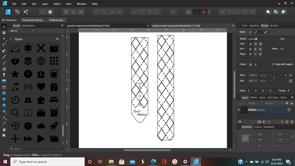
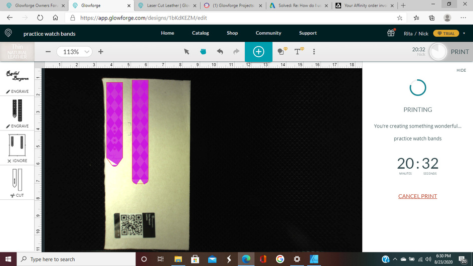
I was just trying to make leather watch bands for the apple watch, so I created a pattern, then I used that same pattern to make an engrave design for it through affinity designer. So first I uploaded the pattern, then I uploaded the engrave design (I will attach photos). I had it all set and ready and at the last minute the GF added this pink mask over my design. I was concerned about it, but I couldn’t remove it without removing my entire engrave design so I just figured that maybe it was normal and it was not part of the design I uploaded so I thought surely it wouldn’t engrave it like that, but it did, and ruined it completely. Does anyone know what this is, why it happened, and how to remove it? The first pic is my actual engrave design and the second photo is what it looked like with that pink layer the GF added.
Were you using CorelDraw or Affinity Designer to create your drawing? (There is a known winding rule issue that converts some Compound Paths into solid white fill for some vector drawings for those programs.)
You can get around it by rasterizing the design before you save it. (Or it might work if you save it as PDF.)
I used Affinity Designer. I saved it as a PDF, but do you still think I need to raseterize it? How do you do that?
I rarely use AD, so someone might have a better answer for you - it has a rasterize option in the right click menu, or you can find it under the Edit menu, but you might have to experiment with adding the parts together before rasterizing it. I’m not quite sure how it works.
Ok I will try to figure it out, thank you so much for you help!
If you want to share the original file, someone can look at it and see if they can find the problem.
As you posted in support, they would need to see it anyway. You can email it if you can’t share it in this thread.
This does not appear to be the same file.
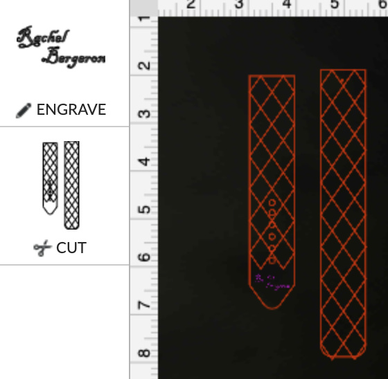
Loaded directly into the GF UI, all steps are the same color and grouped together:
that is the engrave design, which is what I had problems with. The reason it is separate on my GF is because I uploaded just the plain watch band pattern as a PDF that I created through Fusion 360 for the cut. Then I used that pattern in Affinity Designer to create the engrave pattern for it. So I uploaded just the plain watch band file and the engrave pattern file as well and I layered them on top of each other. Is that what I did wrong maybe?
No.
If your intent is to engrave a pattern as shown in your first image (from your design app.), then the simplest way is to convert the engrave pattern to raster/bitmap as suggested above.
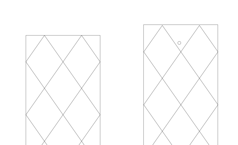
As it is now, you have overlapping vector shapes (shown below) that result in the engrave pattern closely emulated by the GF UI due to how it processes vector shape engraves.
There are steps in Inkscape and AI that convert stroke pattens (like your original design) to paths and shapes suitable for engraving as vectors on the GF, and I am sure CD would provide that capability as well, but for a simple pattern like this, a raster conversion would probably work just as well.
ok thank you, I found a great explanation on raster and vector designs in the community forum explaining how they work with the GF so I think I’m going to study that and then try again.

Look again at the image I posted - that’s all the GF sees, no dashes or stroke width. It only follows paths. If it was set to cut or score, you would just get those lines.
When engraving, it uses something called “even-odd” rules to determine, as the beam passes from one side to another, which areas need to be filled vs. not, and overlapping areas will/can result in lighter/darker engraves. It still uses those precise paths to determine the enclosed object boundaries. It’s not reliable when objects overlap- which yours do, even though only at the extreme edges.
I’m sorry if I’m making you repeat yourself, but if you were trying to make this yourself, what would you do to make it more compatible with the Glowforge to where it only engraves the stroke and no fill?
In Inkscape I would use “stroke to path” which converts strokes (including style, i.e. dashes in this case, as well as stroke width) to paths, like so:
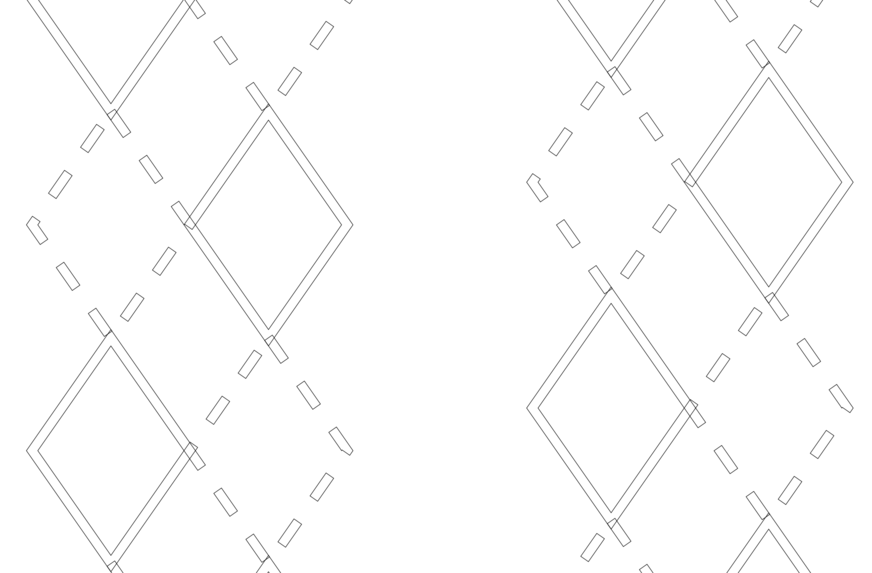
HOWEVER, because of the way these shapes were drawn, there are overlapping areas which would mess with the engrave again - you can see them if you look in the corners where many of them join. So it would not work well with the image you posted. I would have created it differently to begin with in order to avoid that.
The best solution for you at this point is to simply turn it into a raster/bitmap.
The most fun solution would be to recreate the design using your new-found knowledge! ![]()
Hey Jules, just so you know, AD files can also experience the winding rule issue in the GUI. Wish they’d fix the darn thing.
lol yes, that is exactly what I’ll do. I knew they were overlapping a bit but I didn’t know it mattered. Thankfully it’s not a hard design to create.
Yeah, I remembered that it does. I’m just not up on how to rasterize in that specific program. Are you using AD too?
May I ask you what the winding rule thing is with AD? Just wondering because that is all I use.
There are two styles - non-zero and even/odd. One treats all filled areas as solid, the other alternates fill/non-fill. The GFUI only supports even/odd, so overlapping filled areas are generally excluded.
Inkscape uses even/odd by default, no idea what AD uses but it doesn’t matter as it’s how the GF sees it (the paths) that matters.
Either way, I never use filled shapes anyway - like the examples I posted above, I just define the paths and set it to engrave. I can keep track of what needs to be filled myself.