I have had the force of the air assist to move my pens slightly as it’s finishing an engrave…could have been the case here.
I had a similar issue except i was doing an engrave and cut on multiple pieces. I set up the cut and then the engrave centered on about 10 pieces. Without opening the unit the alignment ended up overlapping the cut with the engraved part. Essentially making each piece unusable.
Working on recalibrating the laser.
Usually the only way that would have happened is if you shifted the graphic in the GFUI or shifted the material or perhaps redid Set Focus.
This happened to me to. I think I know What I did.
Set Focus wouldn’t actually change the location, would it? You’d need to actually move it, which is what it looks like they did, probably moved it onscreen to line up with the picture.
3 Likes
The set focus feature does not change the location of a print on the bed, it only changes how the image in the UI tries to align the design with your material.
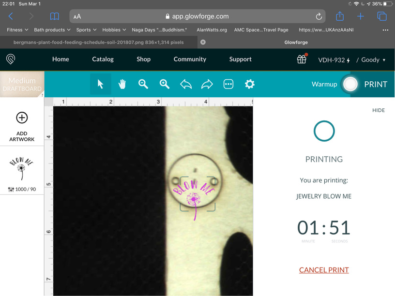
The machine is highly accurate to within 1/1000th inch. Take a look at this print:
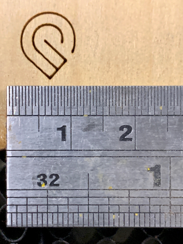
Notice anything? Probably not - it’s TWO prints. I opened the lid after the first one, then turned the machine off for a while. I manually moved the head and gantry of the machine. After I turned it on and it re-did its calibration of the head, I “set focus” to a different height (which did not match my material), and here is what the UI thought my alignment would be (this was at the extreme left edge of my tray).
As you can see, the second print was precisely aligned with the first.
Again, the machine is HIGHLY accurate and does not change print location based on focus settings. Either something moved the material, or you moved the design in the UI.
If set focus was used on the pen for one print, and on the board behind the pen for another print, it seems to me like the height difference would be enough to account for the variance in outcomes here.
It varies the image in the UI, not the head position for the print. That was the point of my post above.
If focus changed head placement, the “home” position of the machine would vary with every material.
I’m not saying it changed the head position. I’m saying it changed the focus height. Changing the focus height for a cylindrical object would change where the engrave falls on the object.
I think. Now you’ve got ME confused.
The beam is vertical no matter where it focuses. The head position determines where it falls,
But it’s also conical, not cylindrical like in your image, and the diameter of the cross-section changes depending on the focal height.
It doesn’t make any difference what shape it is.
The beam will be vertically aligned over the same place between prints regardless of the focus setting. The only thing that can change that is to move the design in the UI, or move the material.
1 Like
I think you’re both right in some sense. Regardless, OP’s screenshot strongly suggests to me that they tried to visually re-align the design with the camera image for the second pass, rather than just running it again without moving anything.
6 Likes
Ok. Thanks for all the laser talk. Lasers go straight unless you put a reflective surface in the path to redirect the energy.
The issue is that I did an engrave and then cut (one push of the button). I did not move/realign the graphics or the material. Everything was lined up before and after the action. The actual engrave/cut was off. This is not a laser issue, it’s a head issue. How do you fix this?
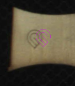
The first image is where I placed the image. Behind the “w” is where it started to engrave the bottom of the stem, moving up.
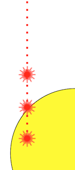
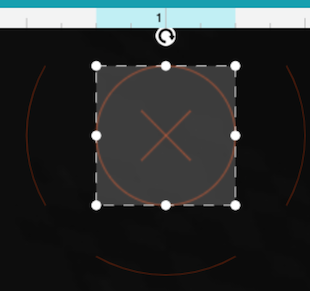
The second image is me conducting Kentucky windage to move the engrave down.
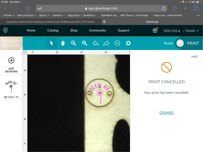
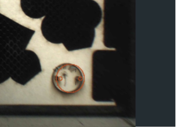
The third image is how offset the cut was, and how it overlapped the engrave.
The laser works fine, the head or software is off.
Your issue is completely unrelated to the OP (edit - unless they had moved the design trying to re-align it with the camera image), which is what myself and others were responding to.
Your issue appears to be that you have not run the camera calibration process. You might want to start your own discussion on that.
I ran it about a month ago. How often do you need to run it?
Once, unless you move the machine.
If you have an issue with alignment, then support can take a look at it - although the specs are for it to be within 1/2" so as long as it falls within that, it’s working as expected. It is not designed to allow you to precisely position designs onto existing printed shapes. You need to build all steps into the same design file, or use a jig for precision alignment.
Many see much better alignment. Mine is about 1mm within the majority of the bed, but the specs are much larger.
(technically I guess spec is 1/4" in each direction from center, as the X has to fall within the 1/2 middle circle)
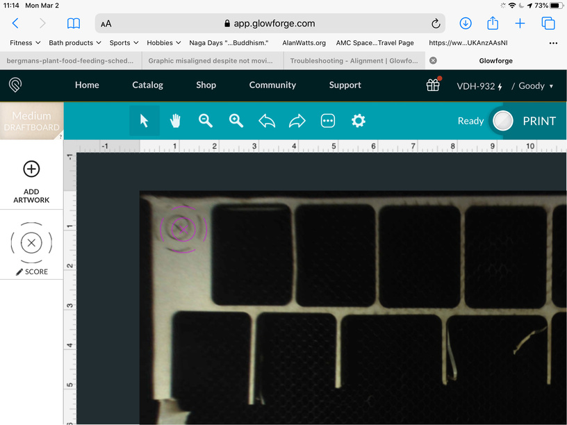
Ok ran the camera calibration and test print. Once complete I printed then”precision preview test pattern”. Once complete the camera took a new image of the bed, it looked pretty good (a little off but still “under” the artwork. Then I refreshed the bed image and it moved. I did nothing to the machine, table, lid, etc. attaching image.
Summary version:
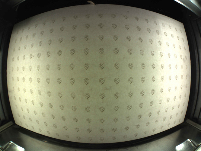
The lid camera sits to close to the bed for it to accurately capture an unwarped picture of the bed…it’s called “fisheye effect”.
This is what the folks at headquarters see when they see a picture of your bed:
Glowforge has an algorithm that recalculates that view and turns it into what you see here:

Which looks more normal for human eyes to work with. So the view that you see on the screen is a calculated result. When you are trying to place something on it, if it is out of sync, you’re going to place the design incorrectly.
It is completely normal for there to be more variance out at the edges of the bed than right underneath the lid camera. But Glowforge gives us a tool to compensate for the fisheye distortion out at the edges of the bed in the Set Focus tool. By clicking with the Set Focus tool right over where you plan to place the cut, it uses that value for the calculations and converts the view at that spot to act as if it is right underneath the lid camera instead of out in the boondocks.
So the correct procedure is:
- Click with the Set Focus tool exactly where you plan to place the cut. (Make sure the little rectangle falls on the material and not off in a cut hole somewhere. If it lands in a hole the calculation will be wrong and the view will be way off.)
- Place the design there.
- Print the design.
It should land pretty much where you placed the design on the material. (Can be off by about a 16th of an inch at the edges - don’t work too close to holes if you can avoid it.)
If you need to use Set Focus more than once, the view is going to change every time you use it. What isn’t changing is the material or previously placed designs…don’t shift them again after you use Set Focus in a different place, and they will still land on the material correctly. But any time you shift the design on the screen, you’re moving where that design is going to land on the material.
The view on the screen from Set Focus is temporary and resets to default every time you cancel a job, open the lid, or finish a print, so after the print, it might look like the print didn’t land where you wanted it to. Judge whether it did or not from the results on the material.
(It can be confusing until you understand that the thing that is changing is what you see in the screen view.)