Decide to do a little exploring while a silicone mold was 3D printing for an experiment, and figure out what the workflow for a laser cutting project from OnShape cad which isn’t the “slightly painful right click SVG export for a face”, which works for a couple of parts, but after a while gets absurd.
So first off made a little laser cuttable box using the “Laser Joint” FeatureScript plugin:
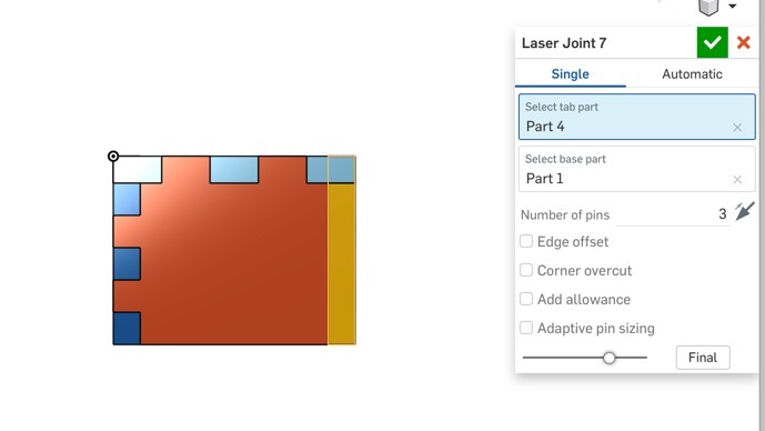
One complaint I have with most laser box makers is they fully tab the box, requiring you to futz with the top to not be tabbed. The nice/bad thing on this plugin is that it only does the intersection you specify (and get’s funky if you try to do more than one common intersection). Since I wasn’t actually going to cut this box (not sure why I would need a tiny box) I didn’t bother to make offsets, etc.
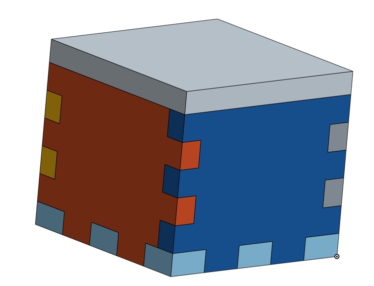
I added a nice little inset for the lid:
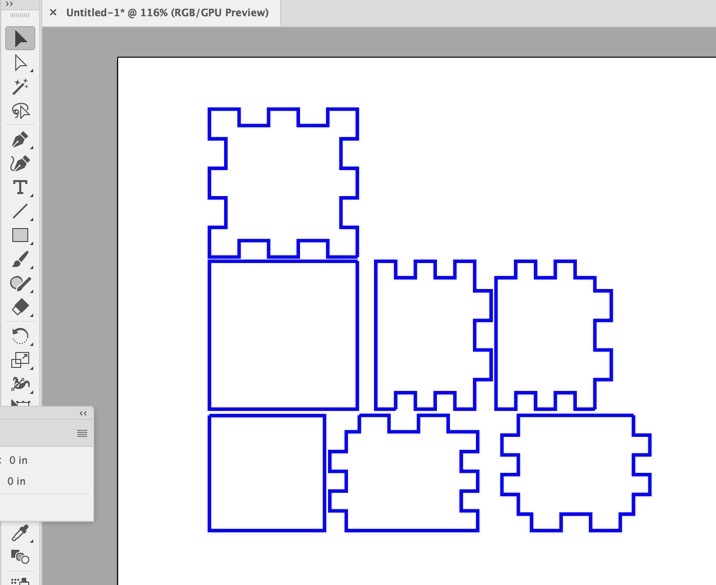
Then I found a nice little feature script called “Auto Layout” which takes a set of parts of a specified thickness and arranges them tightly onto a single plane, allowing you to pre-layout your parts. This is super handy if you have a 3D object like mine, rather than exporting each face and then assembling in AI or inkscape from many SVGs.
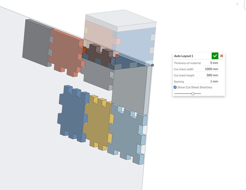
At this point in the feature list, while it all appears to be your fully assembled object, it will now show as a flat layout. But when you roll back time, it gets back to your 3D object, so easy to modify in place.
Then I decided to try out the Kiri:Moto CAM add in (there is a free for low usage) application from the OnShape app store. Imported the already flattened part studio (now this is important, because otherwise it would take your assembly as a 3D object, and slice it like a 3D printer would… So if you want to take a 3D topology map or whatever don’t pre-flatten it and it will slice it into slices, here I just wanted SVG output as one.
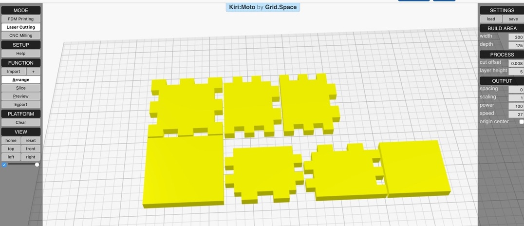
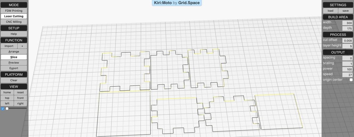
Set it into Laser mode and made some basic settings on the right
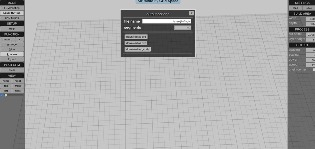
Chose Export, and downloaded as SVG (make sure you have some positive number of segments, which was important as I noted some weird issues if your part thickness and the right hand thickness weren’t the same)
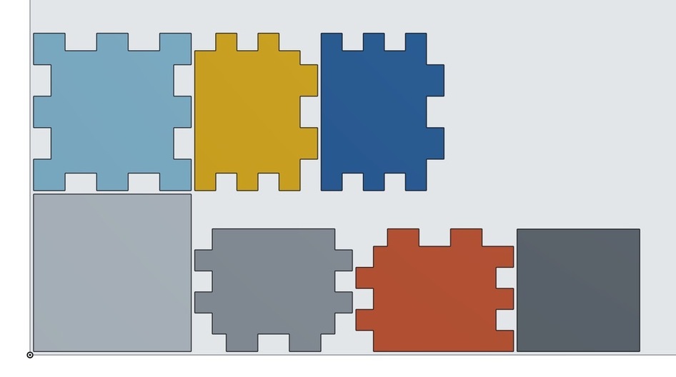
Imported into AI. Now I will note they weren’t laid out in a sane fashion (not sure why it moved things around, since they showed right on the slicer preview), but simple enough to drag them around in AI to make a nice cut sheet.
All told a few minutes work from start to finish, and pretty easy workflow.