I’m taking a break from learning Fusion 360 to learn OpenSCAD, so I’m redoing The Ruler a second time… but this time, with nice things like adjustable height and width and adding a kerf cut.
Not sure if this is properly set up for the GFUI, or if the lines/text are too small. I’ll post the actual OpenSCAD code if some Pre-Release User can test print this and give me some sort of thumb (up/down) report on my line width maths.
Ah, yes. Should have seen that one coming. Easily enough done after I’ve got this tweaked.
Edit: That’s why you shouldn’t stay up until 3am OCDing on code, people…
I’d be interested in the OpenSCAD sketch. I’ve been wanting to do some rulers but haven’t gotten back to it since I wanted both measurements on. I have a local sawmill I’m going to be visiting and I thought I would come with some gifts to sweeten the negotiations.
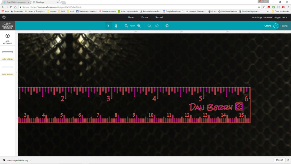
Very nice. This looks pretty good. I would guess that if you engrave the vector tick marks, the kerf of the cutout will trim the ruler such that the ticks are flush with the edges. Nice effect.
The numbers have a lot of nodes. That will be interesting to see how they work out, but vector engraving should be fine.
I’m curious as to what the green fill of the vectors will do in terms of engraving. I have been surprised before by the interpretations of a filled color in relation to power level when I’m doing vector engraving.
This will also be a good way to test vector engraves. I can’t recall at the moment how they work, but I believe it is engraving within the lines. In the GFUI they look thick, but might not actually engrave that way.
One additional comment: when a ruler has both systems, should they be mirrored? So the metric should read right to left so that it can serve as a top when measuring under something. I am always counting backwards when I measure metric! Then put two Glowforge logos, one flipped over so no one is slighted. After all, metric users should not feel inferior. It’s only the Imperial users who have to exaggerate size.
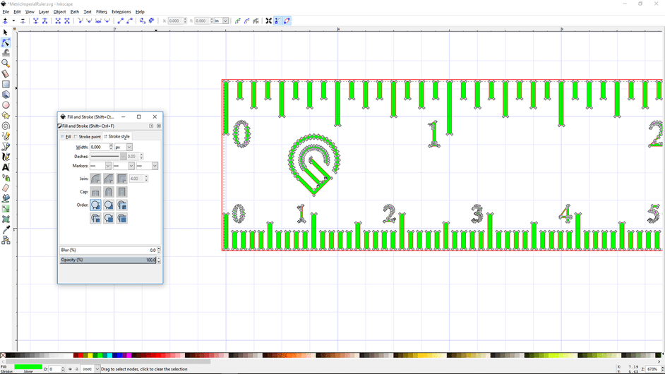
So something I should mention about this SVG I attached, versus the actual output from OpenSCAD…
OpenSCAD currently doesn’t support line colors for SVG exports.
I had to run some parts of my code for the cut layer, and run another part of code for the engrave layer – exporting each respective output as two SVGs – and recombine them in Inkscape by hand.
The (green) engrave layer actually exports as grey fill + black line, I have to manually change it in Inkscape to green fill + no line.
The (red) cut layer also had to be changed from grey+black to no fill+red line.
The large number of nodes in numerals is out of my control, unfortunately. It’s 1:1 the nodes from the actual TrueType font. I can swap in a more basic font like Comic Sans, if needed.
The scale is backwards. That was intentional, because I’m always converting millimeters to inches, and it’s a handy reference. My rational is that it’s easier to use as an upside down ruler than it is to do the conversion maths.
Why inches is larger than the metric scale: You hit double-digits pretty quickly with centimeters, so it was more an aesthetic choice for space concerns of longer rulers. (Did I mention the code can generate rulers of any length?)
I redid the Glowforge logo in DXF before reading that newer dev releases of OpenSCAD support SVG importing, so I’ll probably eventually switch back to the Glowforge-provided SVG file. I’ll rotate the logo 90° counter-clockwise for symmetry, eventually.
It’s a great file. I appreciate the extra work for the color. Although, since it is only the bounding box for the red cut layer it seems you could export it all as one SVG and simply change that one object to a different color, unless I am missing something. You definitely did some work on this because the letters and numbers with counters in them and the right side gear image are filled correctly to leave the holes where they need.
Good explanation of the metric positioning. Didn’t think of that I’m always asking Siri.
It’s a limitation of OpenSCAD. It forces you to work with everything as solid polygons. It doesn’t have a concept of “lines”, per se, except to define the shape of a polygon - that’s the only purpose in it. And every polygon must be a closed solid, unless you run some binary combination (union(), difference(), intersection()) on two+ polygons to make more polygons.
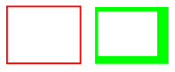
So the short answer is: I had to do it that way so the cut-layer was a path and not “a solid rectangle with smaller, hollowed out rectangle in front of it” looking polygon.
Visual: The left is a path. The right is the aforementioned “polygon with a hole in it”.
And if you try to lie to it about your polygons or the shapes made from them to get the results you want, Openscad will tell you that your design is not manifold (i.e. does not obey the rules for making stuff that can be analysed for 3D-printing with simple math) and refuse to render it properly, or at all.
Thanks for the explanation. I’ve just been working with the letter form outlines using @palmercr’s sketch and @m_raynsford’s flex box and these have had to do some post processing.
@marmak3261 - Just a heads up, I updated the OP based on feedback and concerns I had about the tick marks being too thick (as I wasn’t taking kerf into account when choosing the original thickness).


