I’ll take the 13 files. Whatever it takes to keep Illustrator from ruining it. 
Illustrator seems to take perfectly good DXFs and turns them into faceted garbage. I’m recording a lil’ vid to show what I mean.
I’ll take the 13 files. Whatever it takes to keep Illustrator from ruining it.
Illustrator seems to take perfectly good DXFs and turns them into faceted garbage. I’m recording a lil’ vid to show what I mean.
Uh-oh! I think I overwrote one of them using AI, and I deleted part of the F360 file while I was working on it.
Doggone it.
Let me send you a couple that come straight from F360 instead of all 13 of them…you can see if they are still fragmented.
I’ve seen that myself. Seems to depend on versions of the software and the save file formats. Unless I’m doing something I know is only supported at specific version levels I usually set the outbound file formats to the oldest version the software allows me to save. For inbound formats I set for the latest the software supports. That seems to keep most of the artifact gremlins at bay.
You’d think for the ridiculous amount they charge for their software they could do a better job of simple conversions though.
I had a fairly complex butterfly file that came across from F360 as chopped up open paths in places, and was perfectly fine in others.
I thought I’d just screwed up somewhere…maybe it was the conversion.
(I’m still working on trying to clean it up.)
That’s why this testing is so terribly important up front.
Fun story… at my old job we had a project which had to be submitted in Microstation format. We used AutoCAD. We told them we would do the work in ACAD and convert in the and using Powerdraft (aka Microstation lite). 1.5 years later they changed their CAD standards and when provided with one of our converted files (project still not complete at this point) stated that it would not be compatible.
Essentially, we would have to blow-out all cells/blocks, and all text and dimensions. Then, using the bare linework (which would still have to be converted to the proper colors/linetypes) we could recreate the plan sheets from scratch. We estimated the effort at around $80k. They eventually cut down the number of plans that would be converted, and the estimate was still pretty high ($30k I think). We did a couple of tests and prepped the files for the conversion. Last I heard it still hadn’t been done. (I think the person that overhauled the CAD standards left, and suddenly the requirements became much more lax).
The basic premise of all this is that the way that the two pieces of software tag the data are completely different meaning that if the entity wasn’t generated by Microstation in the first place, then it wouldn’t pass the client’s CAD standard checker.
Remind me to run through my rant about low-volume flush toilets sometime.
(I’m not going to do it now, so nobody panic.)
Point is…sometimes bureaucrats looking to make a name for themselves can cause unbelievable harm. 
Those look great!
Thank goodness!
Okay let me send you the rest of them…the longer arm file might still be messed up - I really did delete the original F360 DXF, but I tried to export that file from AI as a DXF, so we’ll see if the problem is with the SVG conversion in Illustrator if this one looks okay.
Kitchen Brush Files Direct 2.zip (17.7 KB)
(BTW: Got to go hit the torture devices so I’ll be back in about 45 minutes.)
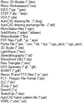
i have had issues in the past with SVG exports from AI when sending them to an older version of Flexi for cutting vinyl. Exporting the same .ai file as an EPS or a PDF was always the fix. Never thought about which software was causing the problem. Can Rhino pull the vector data from a pdf or eps?
Should be able to…it’s something we can test for sure.
It can do both to some extent. I imagine there could be versions of those files that don’t work. Here’s the full list from Rhino v4 (v5 might have more, I dunno).
I’m gonna put a link to your video here so we can find it from this thread too:
Thanks, I was thinking about doing that, but forgot.
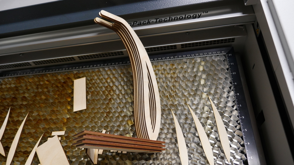
OK, it’s done! It worked… GREAT! I was, honestly, a bit scared that I got too cocky with only compensating for the exact amounts required, but it worked out in the end.
So, I recorded the whole cut process and all the assembly. It’s 20 minutes of video, but it might be interesting for one or two people. Let me know if you want to have the video on YouTube (as an unlisted video) and I’ll take the time to combine the video files and upload them. I also took the liberty of plugging my laser into a Kill-a-watt during this project. The laser peaked at about 430 watts and used a total of 70 watt-hours (0.07 kWh, AKA about 1¢ worth of electricity, not including the exhaust fan).
Anyway, here’s a photo…
And here’s the lil’ vid I did to show compensating for the kerf…
Oh that is SWEEEEEET! 

How was the fit? Did you have to force it at all to get the tabs through the slots?
Thanks to you and to @smcgathyfay for testing these things. You guys are GREATEST AMERICAN HEROES!
(I’d love to see the vid on Youtube if it’s not too much trouble. Or if you wanted to post the two parts as two vids, that’s fine too…whatever is less work.)
Thank you @smcgathyfay!
Thank you @Hirudin!

You’re welcome!
It went together pretty well - pretty easily. I wouldn’t change a thing… IF I was FORCED to change something, I might even make it a tiny bit tighter… But, again, that’s only if I was forced to make a change.
The pieces just slotted together for all intents and purposes. I put all seven tall things into the first (top) layer of the base, and then put all the other layers on one by one. As I put on the layers some of the tall things got pushed out a little and had to be pushed back in, which was a little tough, mostly because it wasn’t easy to get a grip on only one of them at a time.
Alrighty, here’s that video. It’s mostly real-time footage of the cut, so “prepare to fast forward”.
Wow, YouTube randomly gave the video the perfect thumbnail!
The question I almost asked in the video was going to be something like “did you parameterize the length of the tabs as well?”. I’m now pretty sure that you did.
Woohooooo! (I’ll be back in about a half hour! Gotta go watch the vid!) 

(And yes, I did parameterize the length of the tabs - although the difference was pretty small from the original design size in this case…-0.03 mm difference. I designed it for 3.0 mm)
Wow! I don’t think i blinked for half an hour! ROFL! 
That was a fantastic video…my first opportunity to see the whole process through assembly, so many, many, many thanks for taking the time to put it together!
Now I can go and rework the file. I was intially planning to use glue on it (obviously - given the non-attaching base piece) and the tabs were just to get things aligned properly, but it does look like it could use some sort of brace to separate the fins up top - at least if someone is using thinner materials.
Honestly wasn’t expecting it to snap fit together that well either…caught me completely by surprise. I expected more variation from the material not being uniform.
(Original concept was for 1/4 inch thick material, which would have been sturdier, but I love the look of the spaces between the fins too, so this one has kind of evolved as I went along.)
Major Awesomeness! Two thumbs waaaaaay up! 
Wait for it…
Squeeeeeeeeeeeeeee!