I have been creating things my whole life. I have had my Glowforge a few months and have forged pre designed flat things and boxes, and created my own flat things and boxes pretty successfully so far. However, how to accomplish my latest project is being way too hard to figure out. I think I just need a shove in the right direction, or advice on a better tool for the Job.
I currently use Affinity Designer most of the time and Inkscape for boxes and converting images to paths.
The holder for my phone broke and what I need is a piece to replace it that is Y shaped and fits exactly within the base. I need the correct angles for the junctions of the legs, and the correct length and width of the legs. I have no problem with measuring what I need and could hand cut it out, but I really need to figure out how to get the measurements I have to my Glowforge cuz doing it by hand when I have a flashy button is just wrong
I tried some tutorials, but I didn’t find what I think I need.
In Affinity Designer I can’t edit a side of a shape to the precise length unless I do each line individually and then connect them up later.
Inkscape can measure, but I think typing in the correct length in Affinity would be more precise.
The Fusion 360 tutorials lead me to believe that it would be alot to learn and overkill for this project
And now I have been at it too long for anything to make sense.
I am sure that when some kind person points me in the right direction I am going to be surprised at what I have been missing all day.
I would use Fusion360. You are asking for a parametric drawing program and that one is really one of the best for free. It is worth the time to learn it. CAD like that opens up a huge new realm of possibilities.
Another option is to scan the part and convert the part to a vector. That would likely not need any type of measuring if you have a scanner. A GF scan may also work but I don’t know how accurate it will be.
I use Affinity Designer. (If I’m visualizing your problem correctly, Fusion 360 would be overkill, since you’ve already got AD.)
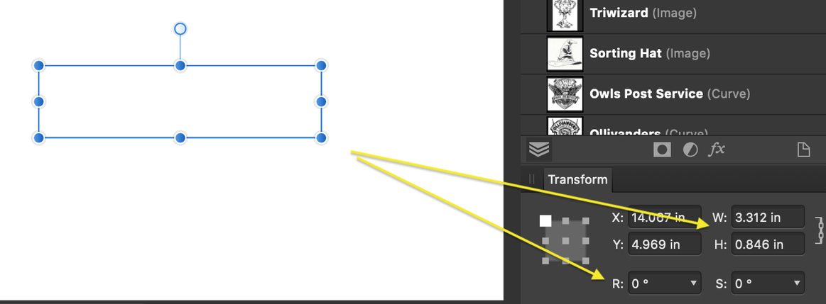
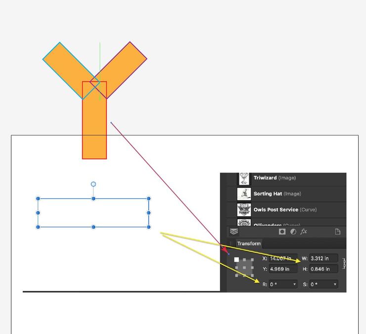
In the lower right corner of the screen is a box that tells you the dimensions of your current shape. (click the little chain thingy to the right of H and W to toggle proportional sizing off and on).
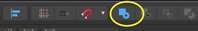
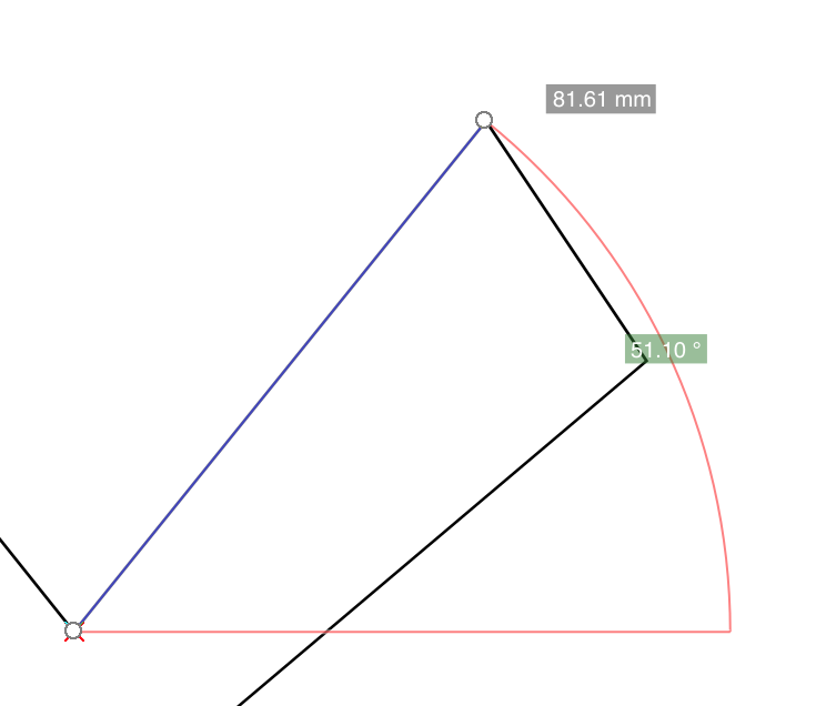
I’d draw rectangles for each leg, make them the length needed by entering the measurement in the box, rotate to the correct angle (angle box is in the same area), then merge them using the “add” function in the top menu bar.
If you want to post your measurements and a photo or something of the shape you need, I can walk you through it with more detail.
I agree that Fusion is overkill for what I understand you are trying to do, it sounds like you just need a simple shape cut from a flat sheet.
I use Inkscape but as G2N stated above, you can manipulate shape dimensions in AD as well. Not sure if you can edit nodes with the same precision, however.
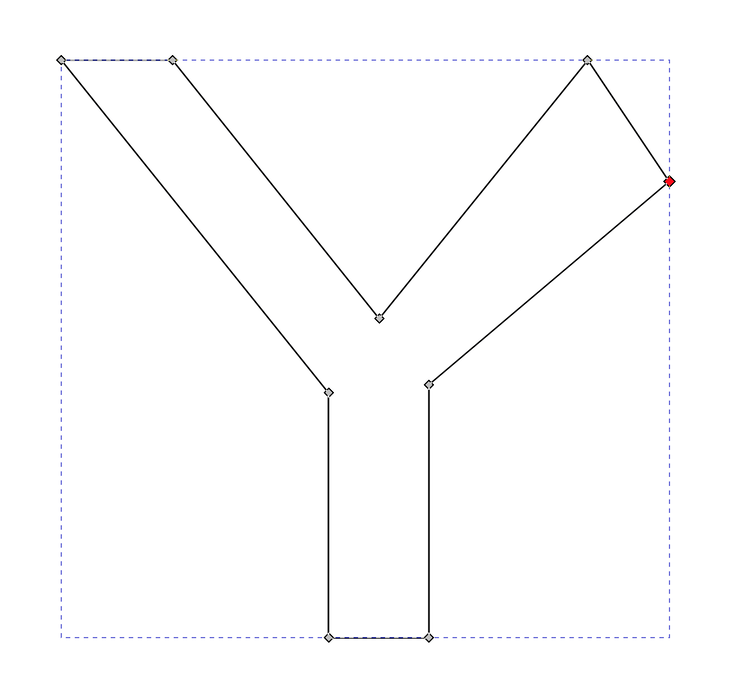
From your description, the fastest (and simplest) way I can think to do this is to just throw a “Y” into Inkscape, convert to path, and manually manipulate each corner. You can use the measure tool to verify each dimension as needed.
Since you want to use Affinity Designer, I’m going to borrow Ruth’s pic and add an idea to it…a “Y” shape is nothing more than 3 rectangles sized the way you want them, with two of the rectangles rotated to the correct angle, and then everything joined. You can use the rotation tools with the little rotational placement box to get them perfect. (Bottom center rotation.) Then just combine them into one shape. (She can show you how.)
Rectangles not Lines!
Thank you so much!
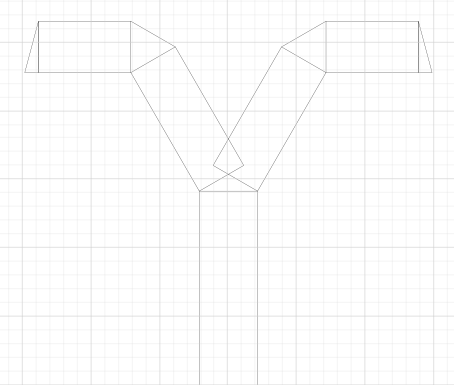
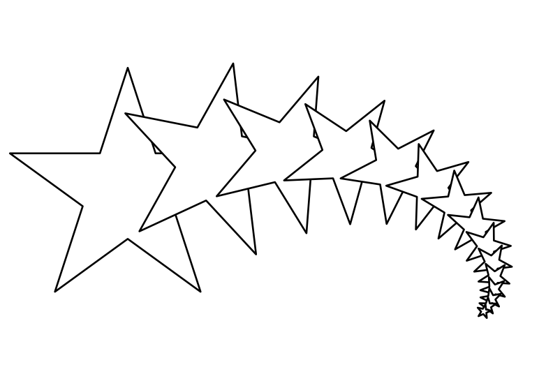
Now to join them up and add the screw holes.
I did build this on a 20x12 so the size would go to the Glowforge correctly.
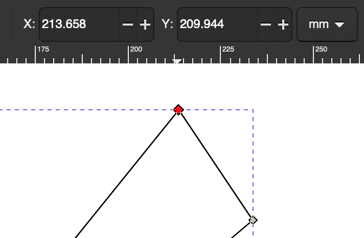
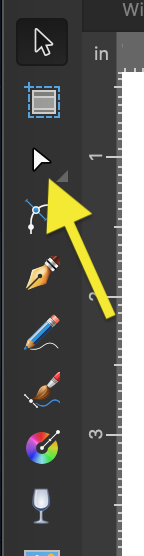
Good job! You can do Layers --> Convert to curves and then use the node edit tool to grab those end lines of the rectangles that come together in the center and curve them out so they overlap, so when they are merged you won’t have a gap. I also overlap anything that’s just butted together, because if you don’t you can get some node weirdness when you add them.
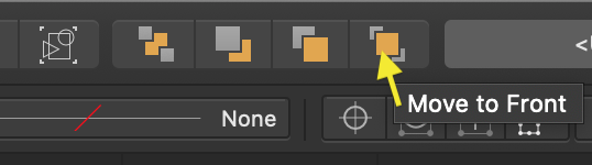
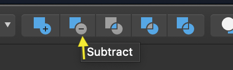
For screw holes, you’ll subtract instead. Make sure the shape to be subtracted is “above” the shape to subtract from, select them both (shift-click), then use the “subtract” button.
Actually, you don’t really HAVE to subtract them, they’ll cut either way. I like having my shapes be one object instead of multiple, but that might be my obsessive tendencies showing through.
Once that’s all done, if you really want to be fancy, you can round off the sharp corners. The curved corner tool is right underneath the node edit tool. Select it, then shift-select each of the corners you want to use it on, then drag one of the corner nodes until you have them as curved as you want them.
Oh, and I should have told you about Cmd-J before – it replicates the selected object, along with whatever action has been applied to it while it has been selected. So if you select an object and hit Cmd-J, you get a copy right on top of the first one, and now it’s the one selected. If you move / rotate / resize it without deselecting it, then hit Cmd-J again, you’ll get a new copy that’s moved / rotated / resized by the same amount again. That can come in VERY handy at times. Like this: