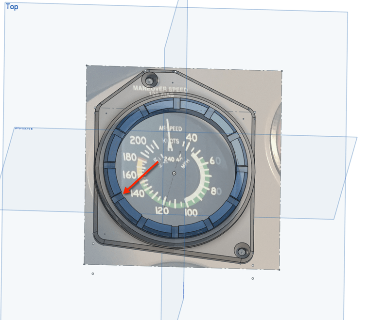
@dan without getting into proprietary information, what is the feasibility of the following. Anyone who does functional 3D printing knows on precision joints (hinges, rotation points or sliders) that the little zits from retractions at each layer are a pain to remove to allow low friction. Would it be possible to use the GF to take the CAD model to trim the surface to smooth. Yes, 220 grit sandpaper does a reasonable job, but with nylon can take forever, and while my CNC is precise enough, it is of course insanely hard to get the registration that precise on an extant object, like this rotating bezel around the airspeed indicator I am making for my father. (and would love to use the laser to cut numbers into the bezel rather than printing…
I always have to use a razor to cut off those retraction bumps. Works quite a bit better than sandpaper for me.
I had a post all typed up, then realized I had linked to a static airspeed bug. I knew there were adjustable bugs out there but could not find it so I deleted the post to avoid confusion.
Point being, should you decide to take the “easy route”, here is a link to an adjustable bug that can be used on any instrument.
http://www.aircraftspruce.com/catalog/inpages/instrbugs.php
Love your design BTW.
That is not an airspeed bug. It is 2 rotating bezels to be a TAS computer (slide rule essentially) with air temperature and altitude to compute the airspeed differential.
Ah, very clever! I am at high altitudes here in the mountains of New Mexico. We have huge differentials of indicated and TAS. We also have very long runways!
My dad has it on the 182 but not the 206, so wanted one for the 206. The biggest pain is the dashboard plastic overlay design (can’t easily get to the screws on the instrument itself - and thanks Cessna for using SAE measurements not metric - ugh). Hence I am attaching using the screws nearby that hold the plastic dash cover in place rather than the instrument itself.
Ooh, on a similar vein, I need to look up the MSDS for UV resins. The support structures generated on a Formlabs are a serious nuisance to trim cleanly, especially if you allow internal supports.
Though not many of those prints with support issues are under the 1.5" limit… hrm.
Personally I am a big fan of good flush cut trimmers/cutters.
This is the most annoying website ever, but the product is good.
https://www.fastcap.com/estore/pc/Pliers-Flush-Cut-26p287.htm
3 Likes
Yes, I have very nice flush cut trimmers which are great for larger objects like support material spots, but those aren’t getting rid of the tiny retraction bumps on the rotating surfaces (and there can be hundreds). Those zits are <1mm in size and way to small, especially on a round surface to trim off. Right now I burnish these, which is painful.
As a hobbyist armchair pilot (flight simulators), this topic intrigues me greatly. One thing I want to do was combine homemade electronics with 3D/lasered parts and X-Plane in order to make instrumentation.
1 Like
could you cut the piece on the CNC to begin with?
Not with an X-Carve (not enough axes) but with a fancier CNC, absolutely.
Depending on the plastic you’re using, might this also be a place for a defocused beam to just slag the little bits down rather than burning them off? I am mostly trimmers and exacto and single-edged razor, but most of my stuff isn’t that precise.
Neat question! I really don’t know, I’m afraid.
Pretty sure defocus would not work for removing the small strands. The energy profile on a laser doesn’t really die off with raw distance, so anything capable of melting a few errant strands would also be enough to goo-ify the plastic underneath that area. And if your strands are trapped in a tiny crevice because that is supposed to be a joint, going gooey is a very bad thing.
Yeah, not talking about defocus, but rather “truing” the surfaces to be smooth like I might with a CNC that could be precise enough. Also depending on the plastic (Nylon is one of the few) you can’t CNC mill them (most shatter)