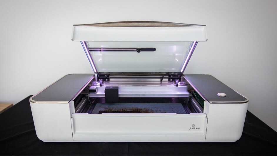
Registration of pre-printed sheets

I have a second related feature request.

Detect objects based on “outlines” and their relative position to each other. Lets say I have 50 coaster designs in a web store. I will then engrave the design you order onto a 4"x4" stone tile. I could fit a maximum of 15 tiles in the glowforge in a 3x5 pattern of tiles, but customers will order any number they want and in any combination of patterns. For this style of feature, I expect to write the software that drops their selected design into a 4"x4" outline and then creates a print file of however many coasters need to be printed and position them in a matrix. This file I create, with between 1 and 15 square outlines and pictures inside the outlines arranged in a grid, would be sent to the glowforge. I would then place the correct number of tiles in the glowforge, in the relative positions as defined in the print file, close the lid and press the print button. The glowforge would find each tile and print on it as per the print file.

As the glowforge communications have said they want people to use it for their businesses, being able to etch 15 (or however many will fit) of something at once in a relatively quick pick and place manner would be a priceless feature. It also is a complementary feature to the discussion on the flooring thread. People would like to etch pictures onto tile that stretch across an entire back splash or floor. Being able to etch multiple tiles at once, without endless fiddling of position relative to each other in the glowforge bed, with a high degree of placement precision is a huge time saver.
2 Likes

That’s my point. The glowforge and the object outline in the print file will never be exactly the same, so it will always be a best fit. But you should be able to attain a best fit that will be precise enough for most applications. The further away you move from circles and rectangles into complex polygons the tougher the algorithm, but I’m good with basic shapes to start. For the complex shapes you could go to some sort of critical set of reference points, but that’s just SMOP to be worked out later.

I’ve seen posts that indicate they aren’t using gcode. At the very least it’s being hidden from the users. They do the conversion of pixels into useful units of measures.

The GF does not use Gcode.

Ah, you’re right. That’s odd.

Well, it seems that I’ve been outvoted. Numbers and math should be avoided because they’re… um… I guess they’re bad or something. I’ll just put a ruler on the screen of my computer if I actually want to move something somewhat accurately.

Its not that they’re bad. It just doesn’t align with their mission (the ease of use part). And who knows they may include tools that help or release more once the machine is actually out and people have a chance to use it.

Also

this sheds some light on it. I know its not dimensioning but its a start.

1 Like

This is getting pretty off topic at this point. I thought allowing numeric input was just an extension of being able to “Shift+click” (or whatever) to move by single pixels. Apparently that’s not the case. I understand now: pixel resolution is reasonable (as long as you don’t count them). I’ll move along.

I believe when people said “What if the lid isn’t 80mm” they were intoning that it is possible to go one better than your request.

You are wanting precise entry of numbers calculated by hand. But if the camera is high accuracy (and the one on the cutting head is), then you should be able to select alignments right in the software.

So I should hope for a feature where I can just tell the Forge “Place center of this cut shape on center of this physical object” and the cameras themselves will find that center and the software align my print.

And “pixel” resolution is absolutely not something that the team would ever entertain (unless I am completely mis-reading them). If they give us physical nudging via arrow keys, they would also give us the ability to zoom in to the point where our on screen pixels are the 0.001" resolution of the stepper motors or smaller. A pixel is not a meaningful measurement of physical world space, unless you also reference the DPI of the image currently on your monitor.

Even if you can enter physical values… you are still a slave to the accuracy of the camera, because it has to find the start point of your measurement somehow. So leveraging the camera as much as possible seems ideal when attempting to get precision work.

3 Likes

I could list 100 examples where software-based feature recognition will almost surely fail. When that happens it’ll be up to the user to make the best of it. I only hope the necessary tools are available to the user when this inevitability crops up.

Personally, I prefer to use hardware and software that gives the power to the user. If the Glowforge is intended to be used by children I hope they add a “Kidz Mode” to the user interface instead of crippling it for everybody.

It sounds like you’re drawing conclusions about what the software is going to do based on the discussion here - I wouldn’t do that. @Tony is going to take all this as advice and I suspect he’ll come up with something both powerful and straightforward as a result.

He’s good like that.

6 Likes

That’s a relief.

I’m afraid of what might happen if too many customers ask for “complicated” features to be omitted.

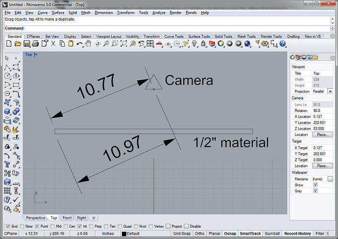
Also note that the camera “distance to edge” will be much different depending on material thickness. So “real world” numbers have little meaning.
This shows a 20" piece of material, 1/2 think. Assuming the camera is 4.5" above bed.
The distance from camera to bottom corner (thin stock) would be 10.97".
The distance from camera to top corner (thick stock) would be 10.77".

Yes, the high res camera can correct for this.

1 Like

Yes, parallax is an issue when viewing 3D objects with a stationary camera. I would hope the macro camera could be used like an optical edge finder.

1 Like

Correct, As I noted above and stated by Dan in this video: (2:20)

2 Likes

I would like two options, one where I can have registration marks on my preprinted item that the software sees (three circles/dots would be easiest I think). This is already available on other laser systems.

the second is where I have options to let me make a line in my image parallel with my material, or centered on my material, ect. Offset from edge would also be nice.

1 Like

I’m with Hirudin - give me a way to specify the positional details. I won’t necessarily use it all the time or even often, but I want the choice.

1 Like

Agreed. Definitely times you want to enter numbers.

Currently thinking about balanced sculptures…

1 Like

In one of the other discussions about alignment of bulk batches, mail merges were brought up. Discussing this with my wife had her instantly drooling.

The idea is that if I wanted to engrave student names on #2 pencils, I could open a pack and just toss them in the forge. Not worrying about orientation at all.

I then tell the forge to locate the shortest flat end (the tip of the eraser) and offset 1.5" in from there, centering with the short extent at that point, and engrave the name selected from the mail merge style list.

With those few commands, boom… my excel list of student names is moved onto the pencils, and they all align flawlessly with one another (sure, some may be on the side which comes factory etched, but if I really care then after my careless toss I just flip a few to ensure those sides aren’t facing up anywhere)

The way I picture this happening in the actual software would be that I use the magic wand to isolate a pencil. I then choose some command which indicates I have just identified an object which exists in multiple, the software asks how many are on the bed, and I enter a number. It then identifies what it thinks is each object, and I have the option to cycle through the list and verify each one (if I select item 5, then a standard mask is overlayed on the display blanking out everything except the fifth identified pencil).

I then accept the identified lot of pencils, and am presented with a nicely straightened out mask on which to align my intended cut/engrave. I select the Mail Merge option, and am provided a standard text box type of selection tool (after locating the file from which to generate the mail merge text options). I click on the spot where I want it to start the engrave (and if I wanted I could select a box area with click/drag, then choose to shrink text to fit, or truncate overflow). If I am satisfied with just manuallly clicking, I can leave it with my first click, but I want things nicely aligned, so I click on the Alignment button, and then select the top and bottom bounding lines, and click center. I then click the edge of the eraser and click offset, entering a value of 1.5"

At this point I click OK, and it shows me a preview of the expected engrave, again I can cycle through each pencil individually and see a masking isolation to check the work. If I am happy, I send to the Glowforge and press my magic button on the unit itself in moments.

3 Likes

Sorry, I didn’t see your retraction footnote until I had already responded.

That’s a great workflow suggestion.