Right side limits not quite 495 mm...causing an apparent right shift of features

[Edit: Changed title to be a better description based on further experiments]

It’s been a while since I’ve posted in the forums. Unfortunately I’ve hit an issue that I seem to recall was also present in some units in the early days, but I don’t recall if there was a specific fix.

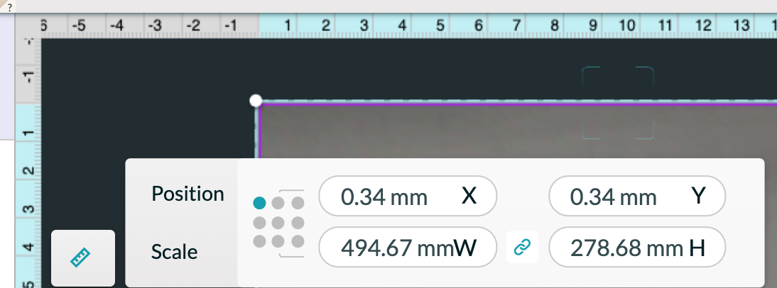
I’m cutting a large design–maximum size 494 x 278. But it hit the right limits while printing. In measuring actual vs. design, the whole x scale seems to be off, causing it to hit the right end-stop and then print everything after that offset in x.

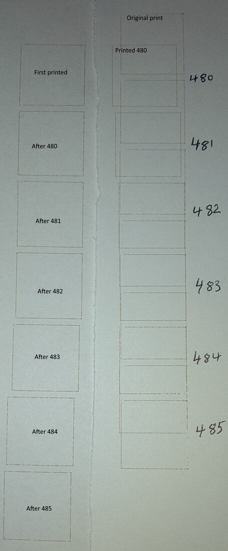
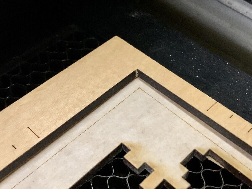
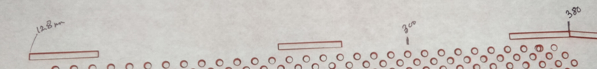
A couple of pictures. to help explain First, the design and as printed from the app:


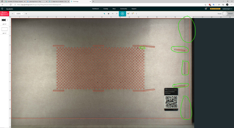
You can see that the design has space between the right-most holes and the edge. I heard it hit the endstop when it moved to print the lower rightmost angle rectangle. It then printed the three small rectangles and moved to print the last 2 tiny holes (upper right of the grid). Note that these printed shifted to the left.

It then moved to cut the outer box.

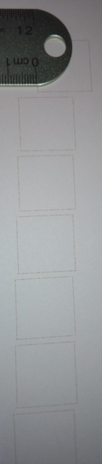
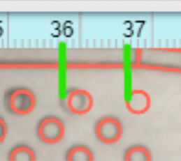
Measuring the outer box, it is 494 mm. So I started looking at other things. Here’s a snippet showing the design against the mm ruler in the app:


Note that the leftmost rectangle starts about 116mm and the joint between the rightmost two boxes is about 367mm.
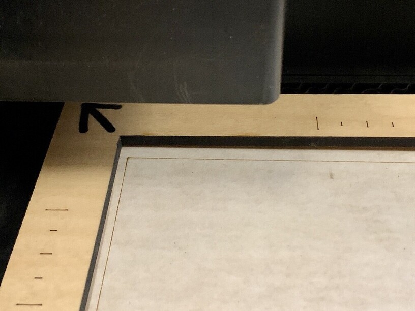
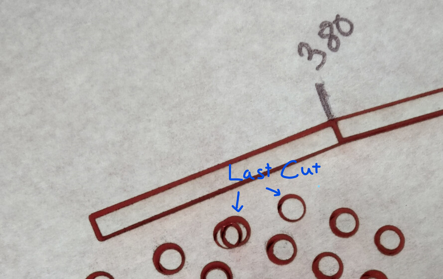
Compare that to the actual printed measurements (measured from left cut line):

measuring in the Y axis seems to be fine.

The design was created in Fusion 360 and exported using the Shaper Origin tool. The SVG was directly imported to Glowforge (and then changed to “cut” instead of engrave for the outer box).

This was the first thing printed today, 6/26/2021, roughly around 3-ish.

NOTE: I cancelled the print when it started cutting the outer box since I suspected it would be printing off (since it was printed last). I restarted the print with just the outer box selected. When it started the cut in exactly the same place, I restarted the Glowforge and tried again, with the same result, so just let it continue.

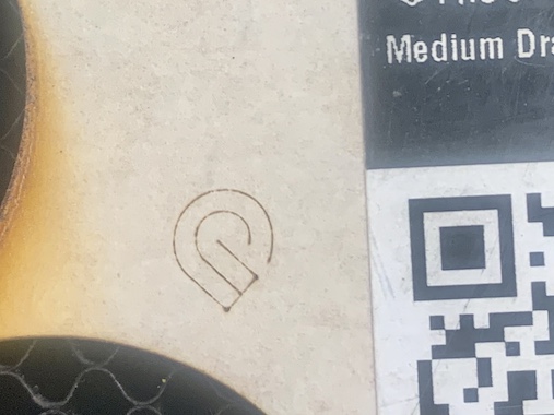
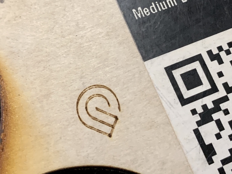
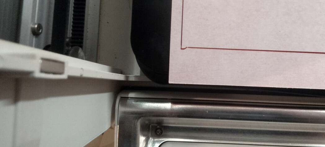
There was also this odd squiggle at the lower left corner:

What can I do to get the X dimension properly calibrated?

1 Like

Did you ever run the Camera Calibration for your machine? If not, it might be necessary to run it, to make sure you have the visual alignment correct for your machine.

And one thing that I have noticed…you are running that size at the absolute maximum width and height that your machine can handle.

So your placement is going to have to be 100% accurate or it won’t work. The easiest thing to do is give yourself a little leeway in your designs. But failing that, select the whole design (CTRL+A) and zoom in by at least 450% on one spot, near the left margin. Then use the left arrow key to nudge the design to the left until it turns gray. (One click at a time.) As soon as it turns gray, back it up one step with the right arrow key until it turns red again. Do the same thing at the top using the up and down arrows.

You might find that the left side and top of the design disappear on the screen, but if it is still red on the screen the whole thing will cut.

3 Likes

Hi Jules, it has been a while. I was wondering how you were hit by the TX power outages.

Whenever I load a design with elements at x or y zero, I have to nudge it to get the app to allow it. I did that here as well…though I didn’t zoom all the way in for the nudge.

I did run the camera calibration a year or so ago when they announced it.

Based on the measurements I took vs the printed actual sizes, it looks like about a 3.54% error in the conversion of x dimensions to X steps.

2 Likes

It was not the best time I’ve had. (Didn’t get a chance to play in the snow at all.) :grinning_face_with_smiling_eyes:

Did you select that outside outline and check the measurements on it in the little Ruler icon?
(I’m wondering if it got a little bit expanded during import somehow?)

1 Like

Here’s the positioning. Looks like it’s running from 1 mm to 495 mm

And it looks like the last to circles printed (after the shift) are shifted left about 9 mm, so that seems to be the steps lost from the right-hand endstop collision:
image
(added the green marks manually to the screen shot.) Not as visible is that the circle to the left of the one marked was double-cut: once before the shift, where it was the 3rd from the right (and is visually aligned) and again as the 2nd from the right shifted to the left. You can see the overlapped circle a bit to the left.

You can also see it better in the expanded photo above marked as “Last Cut”

1 Like

Oh, I definitely agree that the head hit something on the right and bounced. I’m not sure there’s any way to fix it at that size…my workable X axis measurement is only 494.5 mm, so it might still be just a hair too large.

It does show everything as cuttable though, so theoretically it should work. Maybe try slowing down the cut and reduce the power a little? It’s all I can think of to try, otherwise Support will need to take a look at it.

Sorry, that wasn’t much help.

:grinning_face_with_smiling_eyes: Update…I just had my coffee, and I’m actually awake now, so I wanted to mention that the “zooming in” is critical before you nudge. At higher (like 450% and up ) magnification, the steps are smaller than they are at 100% magnification. So you might still be able to shift it over a little to the left.

It might be enough to make the difference here. Worth a shot if you want to test it again on the ruined sheet.

1 Like

Curiouser and Curiouser…
I tried a simple test. Created a 250 x 20 mm rectangle in Inkscape. Loaded it into Glowforge and copied the rectangle, rotating it 90 degrees. This gave me 250 mm in both x and y, guaranteed to be exactly the same since they were duplicates.

Ran a score on the ruined print. These lined up spot-on. So, in general, the calibration isn’t off.

Then I re-ran the failed print (after nudging it as close to 0,0 as possible) as a score on copy paper and it printed exactly the same way as on the PG acrylic. Looking more closely at various dimensions, all of the relative sizes and spacings are accurate. The grid of holes is exactly the right size overall.

It’s just that the positioning of those internal features are 12 mm to the right of where they should be, according to the left edge of the cut… or, probably more accurately, the left edge of the cut is 12 mm to the left of where the design intended.

I think you are correct that the 494 mm is slightly too wide. The actual cut dimension of the outer edge is roughly 493.5 mm. apparently the left edge physical limit of travel is at least 12mm to the left of zero.

Measuring the offset of the two small holes that printed after the initial overrun, they are 9mm left of the rest of the grid. So 9mm of error had built up by that time and an additional 3mm occurred after they were printed.

I have an idea for some more tests to explore where that maximum right edge is. It’s apparently not the 19.5" (495.3 mm) that is referenced all over the place.

So… I created a file with sequenced boxes, each 20 x 20mm. The top row had a box at X=0 and one at X = 470 (right edge 490). Then each subsequint row shifted the left box 1mm to the right up to 495–the max the GF app would allow.

My hypothesis was that each time it tried to print further to the right after reaching the physical limit, it would result in a shift of the subsequent boxes on the left to print further left.

This picture is of the left boxes as printed:

Indeed, the error did accumulate as expected. I got about a 7mm shift on the 2nd row left box followed by 1mm shifts of each subsequent row. From this I can surmise that approximately 483mm is my physical right edge.

Now to test that hypothesis…

1 Like

Once again did a gradually shifting set of boxes on the right side, this time with the right edge ranging from 480 to 485.

The left boxes were printed on the same paper as the first test, but I moved all of the boxes for the 2nd print down about 10 mm.

You can see that box 482 prints barely to the left of the end stop and the left boxes continue to align correctly after it prints. 483 hits the end and you start seeing the left boxes shift to negative positions.

As the Glowforge has no endstop detection, it’s estimating the physical limits of the machine’s boundaries from the camera-based centering after startup (all of these tests were done after power cycling so that the coordinates were reset before each test.

It would appear that my Glowforge runs roughly [-12mm…482mm instead of [0…494]. As the software doesn’t allow designs to be placed in the negative space, that means my maximum design size is 482mm wide (18.97") instead of the stated value.

For Glowforge folks: Is there any way that your per-machine calibration information can get a more accurate correlation between the camera-directed head position calibration and the physical limits of the laser head?

One way would be that during the calibration processes, you mark the zero position, drive the carriage to (or a couple mm past) the expected endstop, then return to zero, mark the new zero and use the high-res camera to measure the distance between the marks.
image

Similar measurements can be made for probing the left, top, and bottom physical limits.

2 Likes

The thing that strikes me that having the accuracy worse at the end of the print than at the beginning and a squiggle at a change in direction suggests the slightest slippage that could mess up big things especially. :slightly_smiling_face:

1 Like

Great testing, as usual…I wonder if re-running the Calibration would do anything to reset your machine boundaries?

Thank you so much for the details. I’m looking into it now. As soon as I have more information I’ll let you know.

There are a couple of separable issues here.

Hardware bounds

I’m still investigating this possibility.

I’m not totally sure that’s the case here yet, but I do have some items that we can address first.

Cumulative Issue

This comment about the error building over time, makes me think you may be seeing an issue with our software where it has an issue with the number of individual shapes in the design.

  • When the design is an engrave it can be rasterized, which eliminates the issue.

  • However, since you’re cutting, the best workaround with the current layout alternative I have is:

Break your print into segments and reducing the number of shapes or images you print at once

  1. When you upload your file to the Glowforge app, each color and each bitmap will become a separate print step. Divide your design into more steps by changing some of the portions of the vector design to be different colors.
  2. Click on a step and choose “Ignore.” Repeat this to ignore all the steps but one, and then press “Print.”
  3. When the print finishes, leave your material in place.
  4. Set the step you printed to “Ignore” and print another step.
  5. Continue ignoring and printing until you’ve finished.

(Related documentation: https://support.glowforge.com/hc/en-us/articles/360044724614-Optimizing-Your-Prints-Print-Steps-File-Settings-More-#printsteps)

Passthrough? - Not Yet

Since you have a Glowforge Pro, another alternative should be to rotate the design 90 degrees, and run it as a Pro Passthrough print. Unfortunately, I looked into that and discovered another problem.

Autofocuser & Head Issue

While researching that other issue, I noticed your print head was having autofocuser trouble.

I made a small change to your configuration that I hope will help that in the short term. If you could try a test print, or even a set focus (no print needed) I’d love to check the logs to see the impact of that change. If you notice things are suddenly worse in some way, let me know and I can easily revert that change.

In any case, that is a short term fix that I hope will get you in better shape until you get a replacement print head. I’m going to reach out via email to sort out those details, but I’ll leave this thread open also.

1 Like

As stated above you appear to have two issues here, one I feel is a processing problem on the GF side, the other is likely mechanical. The former, I printed a similar grid of cuts when I started to have issues with alignment and object shape. It was perfectly repeatable, except it wasn’t the same objects getting distorted or printed where they shouldn’t. Seems there’s a limit on how much “the cloud” can process. Different results every time.

As far as boundaries, my GF cuts the rectangle below, just a fraction under the 495x279 stated limit. It’s likely you could get it up to those numbers but I have never been able to. I cut a “maximum size” rectangle out of a sheet of PG to make a ruler for alignment back in the early days before we had the layout tool. It cuts exactly the same size and location today. My crumb tray seats to within a fraction of a mm every time. I can remove it, put it back, lock a piece of PG against the “ledges” and repeat a print and barely tell it was run twice. Note, I slightly offset my original ruler for the purpose of demonstrating a couple of corners for these pics. It’s cut is precisely the same as the score I ran a few minutes ago.


Just data for your consideration.

Here’s the exported SVG:
drawing (2)

As beating the horse doesn’t seem to be effective, here’s two prints separated by power off, removing material and crumb tray, re-installing.

First print -
IMG_8832

Powered off. Crumb tray and material removed. Replaced. Powered on.

Second print (I think the double lines are visible).

The point is, that’s how precise/repeatable the machine is. Your print limit issue is not inherent to the overall design, it’s something specific to your machine. I’m wondering if your lid camera is significantly offset from the norm.

1 Like

I resized my design to be a few mm inside the limits I determined above and the resulting print was fine, so I don’t think I’ll running into an issue with the number of objects.

Hi Pip,
I forgot to let you know that I did some more printing after you made the change. Things seem to have printed well.

Awaiting the new print head. I think it got delayed by UPS…

Glad to hear it!

I just checked the tracking, and it’s currently scheduled to be delivered tomorrow.

Installed the new print head. Was able to run through the calibration fine. This calibration (four + marks in each corner and center) is different than the calibration I ran way back when (Glowforge logos in a grid all over the sheet).

So I printed the Precision Preview test pattern in the top left. View on the post picture was < 1mm difference. Then I tried printing it in the top right.

I aligned the right edge of the right outer arc at 490mm. When I “set focus”, if I place the focus rect at the right side of the selectable area, the head hits the right end of travel before it focuses.

After restarting the Glowforge and “set focus” a little further left, I was able to complete the set focus without issue. Then I printed and you can see that I again hit the right limits at about 480mm.

I’ve numbered the arcs in the order they printed.

Arc 1 printed correctly and is shown about 1.5 mm left of the preview.
Arc 2 at the top started OK, but at about 480 mm it stopped moving right.
Arc 3 printed mostly in a vertical line, with a bit of curve to the left at the bottom
Arc 4 printed correctly in the Y axis, but is shifted 8-9mm left of where it should have printed
The center cross (5) and the circle are all consistent with Arc 4’s left shift.

Here’s a higher quality picture of the actual printed pattern:

[Edited to add:] Printed on Proofgrade Draftboard