That’s a great write-up! I keep forgetting all the cool little gimmicks that Inkscape has up it’s sleeve. And the great thing is, the resulting SVG is in the <50 KB range and no longer the >1 MB monstrosity. 
3 Likes
Genius! I wonder if it works similarly in Illustrator.
1 Like
That is a much more simple and easier way then I do with a great result. Thabks for putting that together!
1 Like
That is a great alternative but just like I found useing the spiro tool and making clones and re sizing is that in the next size up and put etc they are all the same. In the fusion using spine the geometry are diffrent per layer they aren’t just the next size up
1 Like
Indeed, the problem is that the source image is too big for our software (and many other programs!) to handle. Thank you for reporting it; it will help us improve our software.
There’s some great Inkscape advice here, too, so I’m going to move it to Beyond the Manual.
6 Likes
Make your inner-most squiggle with whatever params you want, then your larger outer-most squiggle lessening the Spoke Ratio, then use the Extensions > Generate from path > Interpolate… feature to create all the steps in between, including the blend between squiggle amount.
In Illlustrator you can use the Blend function to do the same.
For both of these, it helps to have the same number of points in the star objects, but they don’t have to be (you’ll get varying results, if at all).
13 Likes
Ha. I was wondering how to do this automatically. I was doing it ring by ring adjusting the ratio and generating the next. Then you have to align them. Hang loose and I’ll do this.
2 Likes

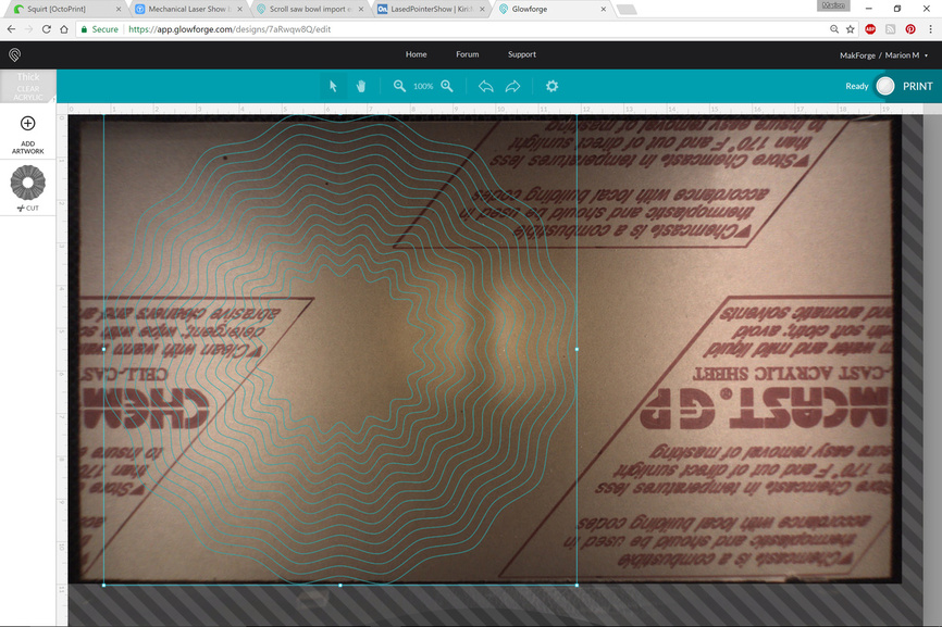
You beat me to it! I used for the starting center .85 for the ratio and outer ring .950. Did 14 steps. Inner is 4" and outer is 11". Any tips for aligning the inner and outer correctly? [SVG here:]

5 Likes
Your all making me jealous right now as I am stuck at work
Thanks @mpipes for doing the test validation. If your laser is powered up what is the opt time estimator say for pg maple ply? At 11inch diameter
3 Likes
Is there any information on how big of an image the software can handle?
2 Likes
Not Rita, but I can take a shot at explaining it if you would accept my word for it…we had the same trouble with the digital cutter files created in CAD programs.
From @Clone 's original file that came from a CAD source you have a file that looks like this:
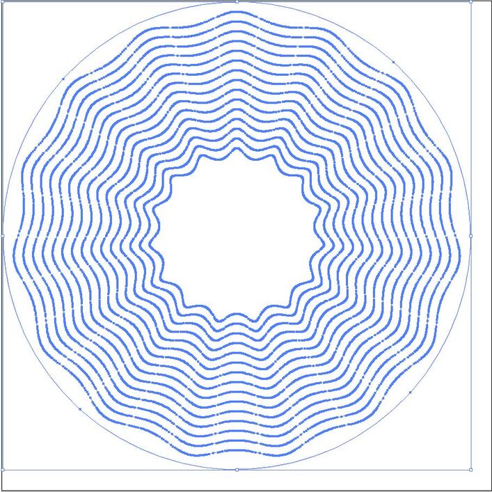
That has something like 30,000 nodes or so.
From the 2D vector drawing software you get an equivalent result that looks like this:
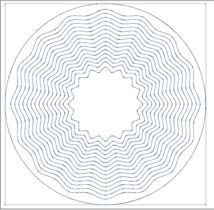
Haven’t counted them, but it’s a lot less than 30,000.
Most software has trouble with the first one. Not so much the second. You just want to keep the nodes to a minimum where you can.
The 2D vector programs have routines that can simplify the number of nodes if they are joined. The problem with a lot of CAD programs is that they don’t always export the paths joined. And if you’ve got that many nodes, joining them becomes impossible.
It’s generally more of a problem with curved lines though - so if you can design for curves in the 2D software you’ll have a lot less trouble.
4 Likes
I created the inner path. Hit Control-D to duplicate it directly in place. Then hold down Control and Shift while you scale it. Shift causes it to scale about the center point, Control constrains the aspect ratio, so the larger one stays aligned to the smaller one. Then adjust the curviness/ratio of the larger version as needed.
I’m getting 12:42 for time. The path display is showing it will cut the largest ring first. Might see if there’s a way to make it cut the inner first to avoid any possible shifting, particularly if you have any warp in your material. Maybe Inkscape has a “Change Direction” function for paths but I’m still green enough I’m not seeing one right off. I know other design packages have the feature, I’d expect Inkscape would too.
Nevermind I found it. Have looked at it a hundred times. Hahahahaha… They call it “Reverse”… but now the server/app is timing out so I can’t see if it changes the cut order.
5 Likes
Or you can manually switch the cut order in the GFUI. Tedious, but it would do it
If all the paths are the same color you only get one cut object in the GFUI.
However, if you make each line a different color, then it splits them all up into individual operations. In this case, there is no need to order them manually. The GFUI will automatically order them the way you want if you use the Inkscape color palettes that forum users have put together.
4 Likes
OI. you are completely correct, I just automatically assumed that each “ring” was a different color. And even then, didn’t think about the specific ordering of colors.
1 Like
OK, so “Reversing” the direction of the path in Inkscape WILL reverse the direction the laser takes on that path, but does not impact whether it cuts the inside or outside ring first, so it seems it’s up to using color to change the order.
3 Likes
Ok. That is simple enough. I was making a new object and the points rotate in relation to the first one. Duplicating then makes it exact.
Book this one done! Thanks for everyone’s help.
Looks like the outer circle at 10.75" is about as big as you can do at one shot for the GFUI sizing limitations.
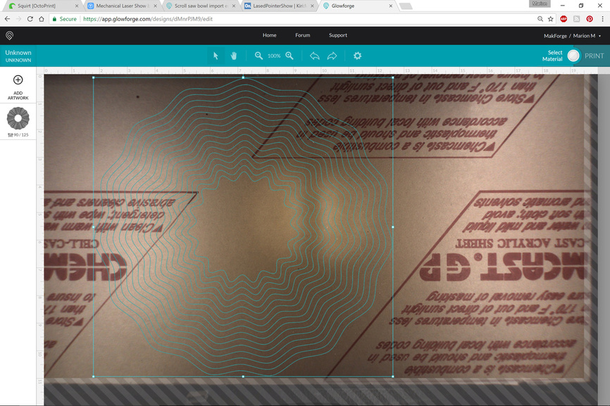
5 Likes
Add or remove one more star point and you’ll be able to eek just a wee bit more size out of it. See how the top has one point at the edge of limits, but the bottom has two points at the limits? If the Top had two points directly mirror-image of the bottom, you can maximize it.
1 Like