Squares not square (Replacement unit fixed problem)

UPDATE: Glowforge replaced my unit with zero hassle. The new one does not exhibit this problem. (Thanks, Glowforge Team!)

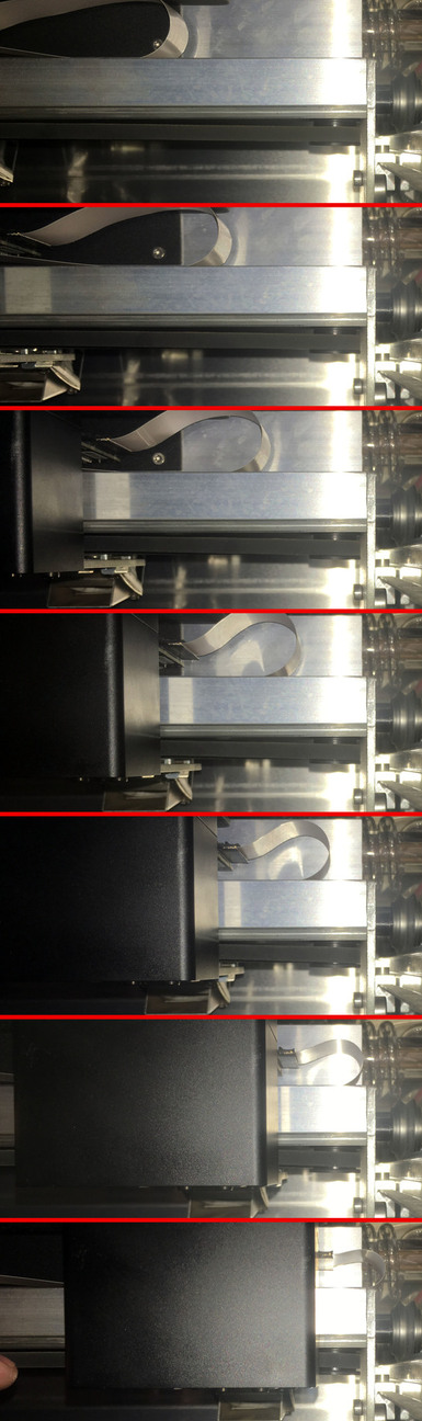
If you are curious about the methodology I used to quantify the problem, and the great insights shown by others in identifying the underlying hardware fault with my initial unit, read on…

In doing some inset testing, I created the simplest of files: 3 squares at slightly different sizes: 10.08 mm, 10.0 mm, and 9.92 mm (basically, 10 mm +/- 0.08 mm). I was trying to see how much I’d have to adjust for kerf to get Proofgrade acrylic to nest perfectly.

In measuring the resulting test squares (and the associated holes) with my digital calipers, I discovered something odd: all of the “squares” were actually rectangles. They were the expected height in the vertical direction (accounting for kerf), but all were narrower in the horizontal direction. The difference was significant, such that all of the “holes” were less than 10 mm wide.

For example, my “10 mm” hole was 10.08 mm high, but only 9.57 mm wide. The others had the same discrepancy. I double-checked my source file, and I also tried again with another file as a test. The results exhibited the same behavior, in that the horizontal width was much less than expected.

Here’s the file, if someone wants to sanity-check my results: Inset fit test.zip (1.3 KB)

While the absolute value of the error isn’t large in this case (~ 0.5mm), that still seems huge compared to the expected level of precision. (As an aside, I am aware that Inkscape reports the size of objects in an odd way; it includes the stroke width, which I compensated for. Even accounting for that, square objects should still be square, right?)

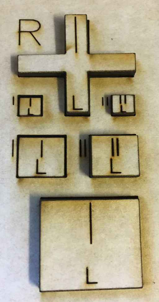
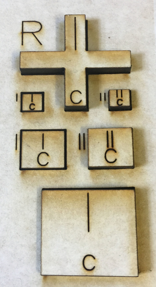
After I wrote the above, It occurred to me that perhaps the error had something to do with where I was placing the squares within the workspace. (In order to efficiently use scrap, all of my test squares had been placed at the far right edge of the printable area.)

I did another round of testing using a single 10 mm square, duplicated within the Glowforge web interface and cut at various locations. The results were informative:

  • Out of 5 duplicated test squares, all had the same dimensions in the vertical direction (within 0.01 mm).
  • They were all “full height”, accounting for kerf.
  • In the horizontal direction, however, the widths varied.
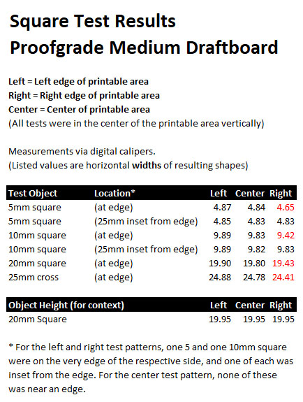
  • The squares at the very edge of the printable area were narrowest: smaller than expected by about 0.5 mm.
  • For squares a bit farther away from the edge, the effect was less pronounced.
  • It wasn’t until I reached ~3 inches from the edge that the “squares” actually became square.
    UPDATE: based on later, more rigorous testing (details in additional posts below), the effect may actually be limited to a narrower band near the edge.

So… unless I’m mistaken, a given design will not necessarily print at the same size anywhere within the printable area. Near the edges, it will be narrower than expected. For macro-scale projects the error is probably too small to notice. But it could definitely create problems for detail work.

  1. Has anyone else noticed this behavior? I’d like know if it’s unique to my unit, or represents a general issue.

  2. Assuming it’s not unique to me, is this behavior already known to Glowforge?

  3. If so, is it considered a “bug” that will be corrected, or is this behavior expected?

  4. Other than avoiding the outer edge of the printable area, is there any practical way to compensate for this?

Thanks for listening. :slight_smile:

12 Likes

Very interesting.
Let us hope we get some insight from P&S on this because those discrepancies are quite unexpected

2 Likes

I haven’t seen anybody report this before. Dimensions should be consistent everywhere.

If you do a bigger square does the error get bigger or remain about 0.5mm? I.e. is it an offset rather than a scale error?

Is the belt on the X axis tight and running straight? If the anchor point on the carriage was not in line with the pulley then I think it would slow down at the ends. It would need to be a big offset to make 0.5mm difference though.

Another thing to check for is backlash. If you cut a cross it will be travelling in opposite directions doing opposite limbs. If there is backlash the limbs will be out of line with each other.

4 Likes

Very interested to hear the response from support on this.

2 Likes

I really don’t remember this being reported before. So I did a search and didn’t find any one having a problem like this. But I did find:

and

The first one would have shown this problem because 1) they are making some squares close to the edge, and 2) they rotated the grain, which would have caused the discrepancies to accumulated.

If anyone wants to test their machine they don’t need calipers to see the effect, they just need to keep track of the orientation and make two rows of a chess board.

It will be interesting to see what support has to say. I mean, after they ask ‘Was this on proofgrade?’ and ‘Try it again and make sure your material is flat.’

2 Likes

If it’s near the edge of the bed it could be due to forced deceleration. Sounds like there’s a good chance that’s the case.

1 Like

If it is cutting and not engraving it should not make any difference. When cutting it always decelerates to stop at a right angle corner. No reason to do anything different if the corner is near the edge because it doesn’t overshoot.

2 Likes

I think some of the squares I cut were close to an edge. All my squares were exactly the same size as far as I know. I did not measure them with calipers.

1 Like

I’ll do some more testing, but to verify a few things:

  1. This was Proofgrade (medium clear acrylic). I used the automatic cut settings.
  2. Everything was dead flat (locked down with magnets).
  3. So far, I’ve only tested the right edge of the printable area, and about 3" inset from there. I’ll check the left side as well.

I agree you could probably detect this without calipers, if you mark the squares with an arrow before removing them. For the squares closest to the edge, they easily “fall through” the holes they were cut from if the orientation is kept the same, but they get stuck if you rotate them 90 degrees before putting them back in their own holes. (They can be forced through without too much effort, but it’s clearly a much tighter fit in that direction.)

1 Like

Mine were not proofgrade. They were 1/4" hard wood and 1/8" baltic birch ply.

If I recall correctly, the GF cut on the left side of the machine for the 1/8" stuff, and across the middle of the bed for the 1/4" stuff from left to right. The 1/4" was a long narrow piece, which I placed horizontally across the bed.

More testing – this time on Proofgrade Medium Draftboard
(a story in pictures)

Setup

Identical patterns for Left, Center, Right of printable area:

Square Test.zip (4.6 KB)

Preview Image:

Visual Results

Overview:

Right-side objects placed in Left-side holes:
(Note the larger horizontal gaps.)

Left-side objects placed in Right-side holes:
(Edge objects fail to fit.)

Center objects placed in Right-side holes:
(Edge objects fail to fit.)

Numerical Results

Observations

  1. There’s definitely an issue with objects being too narrow near the right edge.
  2. The error appears to be absolute, rather than relative to object size.
    (The 10, 20, and 25mm wide objects show the same magnitude of error. The 5mm object shows a lesser error, but I think that’s because both edges of the object are within the “error zone.”)
  3. Interestingly, objects on or near the left edge are consistently wider than at the center (although the difference isn’t as large as with the right edge discrepancy.)
  4. All three locations showed identical object heights (comparing the 20mm squares).
    (Although notably, this height was larger than any of the measured widths for these same squares.)
14 Likes

That’s very interesting! You have a neat methodology.

I wonder how close to the edge you need to be so see this effect.

1 Like

What does the X belt path look like when the carriage is on the right? Does it remain parallel or does it start to slope when the carriage gets close to the pulley?

2 Likes

By X belt, do you mean the one that is located on the underside of the main gantry? I’m happy to look, but I’m not quite sure what to look for in terms of what alignment is correct vs incorrect.

Yes the belt that drives the carriage along the gantry.

The side of the belt that drives the carriage should be exactly parallel to the rail the carriage runs on. If for example the pulley on the right was offline the belt would get progressively slanted as the carriage approached and that would cause it to travel a bit less.

It is called the cosine error because instead of moving distance X when the belt moves distance X it moves X times the cosine of the angle of slope. As it gets closer to the end the angle increases.

I have no idea if that is your problem but it would give the symptom you have.

9 Likes

I think you may have diagnosed this one! Is this what you are talking about?

2 Likes

Hm. The belt on mine stays up at the top of that pulley all the way across. I guess that’s a data point, but I haven’t tested whether it cuts square squares.

Oh yes, classic cosine belt error and you don’t want the belt rubbing on the pulley rim. Looks like the pulley is leaning due to the belt tension. On my 3D printers I run my belts in a vertical loop so that gravity isn’t a factor and I shim my pulley and motor mounts to ensure it runs in the middle of the pulleys.

7 Likes

It doesn’t seem like that small amount of misalignment would matter, but, sure-enough, the math (my attempt at it at least) checks out. The position of the belt being off by 4mm (maybe even 3mm) would be enough.

5 Likes

I also checked the left (drive) side of the x-axis pulley, and like the right one, the belt rides on the lower portion of the wheel. However, on the left side, the lower portion of the wheel seems to be in line with the head rail, such that everything remains parallel as the head approaches the left end of its range.

On the right side, it seems like the pulley’s lower position creates a definite angle between the belt and head rail, which becomes larger as the head gets closer. I tried scooting the belt upwards toward the top portion of the right pulley, but it just immediately returns to running on the lower part – likely due to both gravity and the tension-induced lean that palmercr describes.

As a newcomer to lasers, I’m definitely developing an appreciation for the engineering challenges involved with such a precise instrument! Overall, I am loving my Glowforge, and I have already made many wonderful things with it. That being said, my overall expectation is that dimensions should be consistent throughout the printable area (within defined tolerances).

  1. Is the behavior exhibited by my unit considered a defect by the Glowforge team?
  2. If so, then what can be done to correct it?

(If it’s not considered a defect, I’ll have additional questions…)

1 Like