figured I would try to link out to a new topic for people trying this.
so I have tried this and its neat and all but I am having some issues / feed back
this very well could be a PICNIC (problem in chair not in computer)
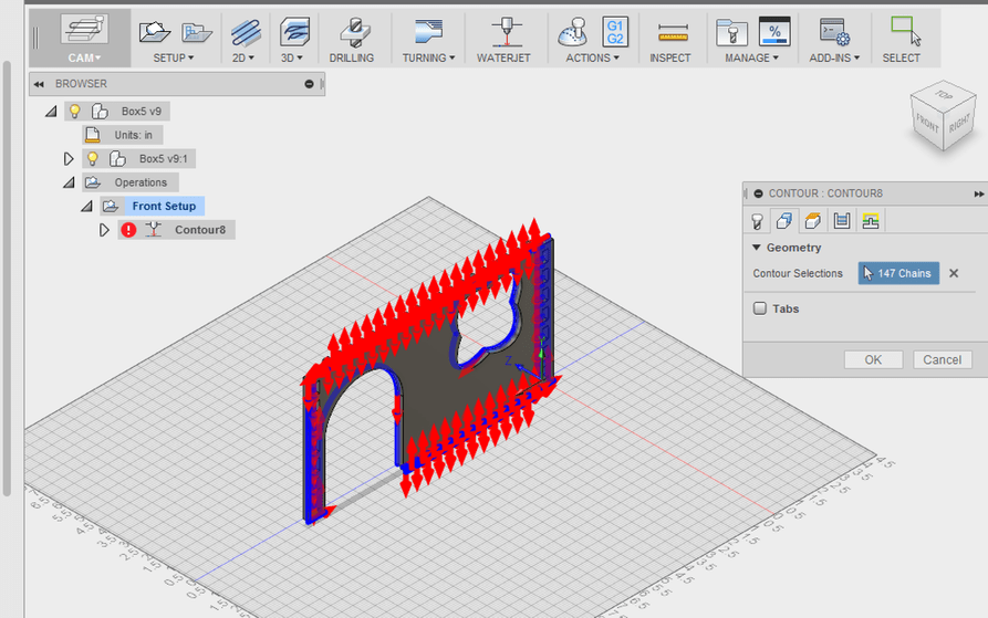
I have dozens if not hundreds of tabs to lock into the next part. I am having to select each face of each tab (it was something like 163 items to select). it would be nice if I could click the face of the plate and it would find the outer boundaries of the body
selecting slots was easy as if I hovered correctly it gave me a void and when I clicked it, it found the boundaries. and put the cut in in the scrap.
for all the tabs the cut it is in the wrong place it is putting the cut in on the body side instead of the scrap side.
it does not appear to be coming up with that great of a motion plan more of a motion plan based on the order I selected the edges
I am not sure if the cut ins even mater as it will be going to svg anyway and then the motion plan will be handled in GF anyway.
all the clicking is pain full and prone for miss clicks or miss’s
Can you send me a link to the file and I will see if there is a good way to do it. There are a few kinda hidden tricks to select things in CAM and I will see if any apply here. If so I will make a video to show the process. That said, it also may be we need to work on the workflow to make it easier as well
eh… not sure about a link (i dont know what a link is)but I added you back to the project. I was just trying the front
I have being using box 5 for the house and box 4 for the bridge and towers. but to play with the came I was only using the front on box 5. that is still in cam mode if you want to poke at it with its million finger joints
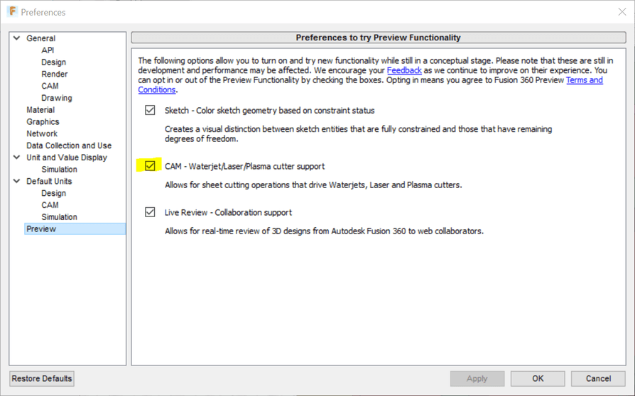
This is great thank you, it explains the loop select. I don’t believe at home I had those check box’s selected so when I clicked the faces well they where not clickable. it looks like the tool is still placing the lead in on the keep material but that really doesn’t matter as what we are really trying to do is get the lines for a SVG. this is also better then exporting a sketch as dxf to then import it into ink scape and having to compensate for 2.54 drift
In the video, selecting “Right” didn’t seem to work. Was there a bug or something, or would it have just been a matter of regenerating the toolpath or something else? Maybe selecting each set of outlines (inside and outside) would have fixed it? I’ve only been using my current laser cutter for about a week now, but having to manually offset all the lines is already getting old!
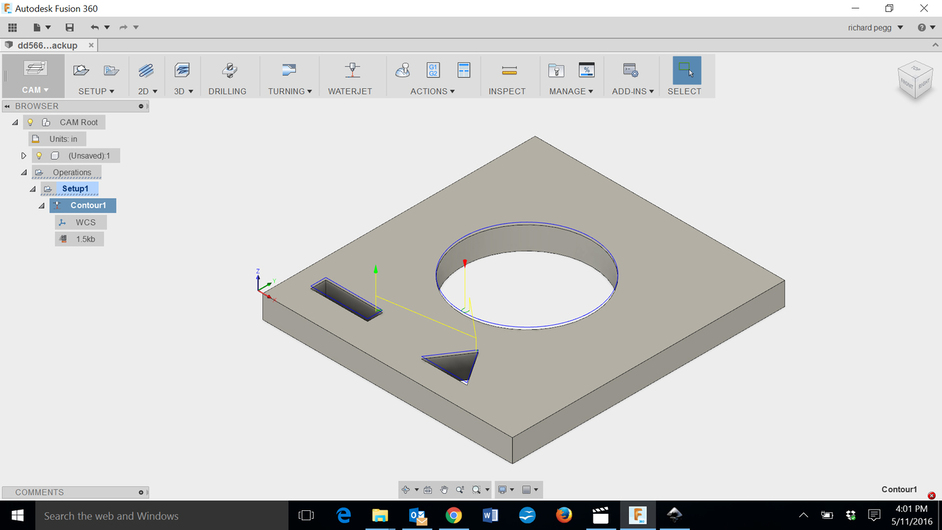
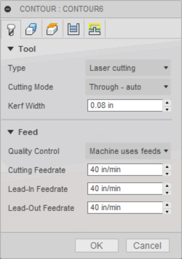
For me selecting right compensation on the contour tab generated an error. Selecting Center seemed to work up until exporting the SVG. When I opened my SVG file the circular cutout of the three (square, triangle, circle) was not in the SVG image. If I selected left compensation then everything was visually generated fine in the SVG. The simulation runs for both left and center looked just fine.
BTW: The options on the contour tab were significantly different that the video showed. Under Geometry the Inner and Outer Loop selections were not available. And the “In Computer” compensation type was only available for the left sideways compensation. Thinking the software folks are still playing around with that section.
Strange…I have have reached out to one of our Product Managers to see if he knows why these aren’t available for you. Looks like you are on a Windows PC and I am on a Mac, let me try it on my Surface in a bit as well.
I am using the shipping version that’s available from our Fusion 360 site. I have verified that I see the options on both my Surface and my Mac. Still not sure why yours are different.
I think you have already done this but I have a few questions.
yes all my setting match your print screens but I don’t have the check boxes. I can see the loop that you put on it but in my geometry it shows nothing selected for bodies but it does show your blue outlines that you where able to place
Looks like we may have narrowed this down. I am running the same build as you guys although I have a few additional beta options available on mine through an internal text command I forgot I was using.
This isn’t something we are ready to turn on outside of the team just yet as it’s not ready for prime time but this raises awareness of the need for it especially with laser cut models like the one you shared.
Let me know when I can send a t-shirt and size and I will get one to you in the next few weeks.
So… Is there going to be glowforge support in fusion 360? I currently use it as my CAD/CAM for both of my CNCs & Plasma cutter. And was planning to use it for CAD for the Glowforge. Then use the web component to upload the DXF that I create in it. But the thread title has ‘CAM & GF Post Process’?
As far as I knew the Glowforge handles the CAM/PP with-in it’s own cloud? And IT would act as the CAM/PP for ‘traditional’ vector apps and the likes. F360 has a ‘database’ of pre-canned PP and has the option of customs ones. I had to do that to add 4th axis support for one of my CNCs.
Direct glowforge support in F360 would be interesting/handy.