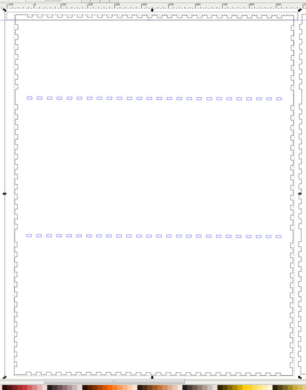
So I wanted a shelf for my coffee products next to my coffee pot. For a starting point I used a TrayLayout from festi.info/boxes.py. (TrayLayout - Boxes) and generated a SVG file to load into Inkscape.
I want to turn the generated box on it’s side to give me a column of 2 cubbyholes with a top that has a border around it so stuff doesn’t fall off. I could just use one compartment side by side and three high and leave the top off, but i decided to trim the upper fingers off using Inkscape’s Path / Difference operator.
I don’t know how to provide a link to the festi page with data I entered, but this is the generated SVG
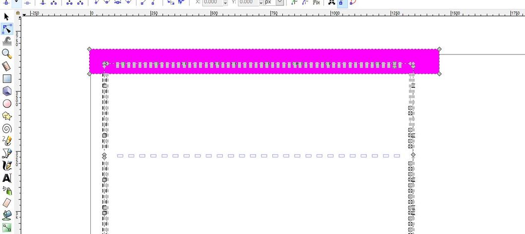
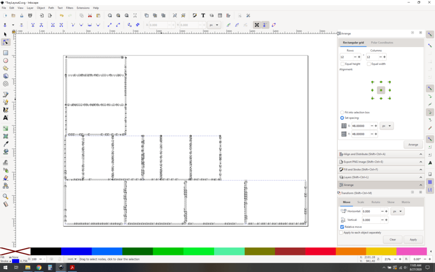
This is where i have problems. I tell Inkscape that the back or sides are the bottom layer, and the box to cut is the top later, but the Difference operator is ignored. I have tried Grouping and Ungrouping, but the best I have gotten is if i ungroup the panel, the area to difference is cut, as are almost everything else except for a few fingers (so not just the top quarter centimeter, but the sides and bottom).
I have attached a image that shows my setup.I have been fighting this problem for a few days.
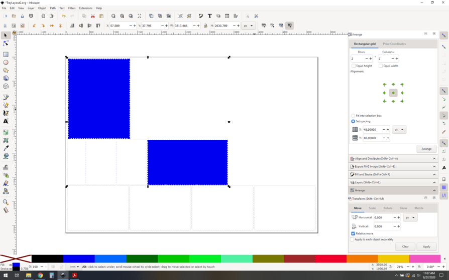
So, I’m not quite sure what you are asking, but I downloaded your svg, and from the photo it looks like you have the rectangle to the top in the photo. So, make sure when you made your rectangle that you clicked object to path. Then, the main figure you want to take the difference from, I had to use the node selection tool to select it. When you can see the nodes, you can do union or difference with no issues. I hope this helps, I was able to do the difference for your file when I use the node selector tool.
Here is the before and after, the colors don’t matter, it’s just my default rectangle.
I had tried to object to path without any luck, but had I had not tried nodes (I am new to Inkscape and don’t know anything about them.
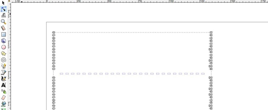
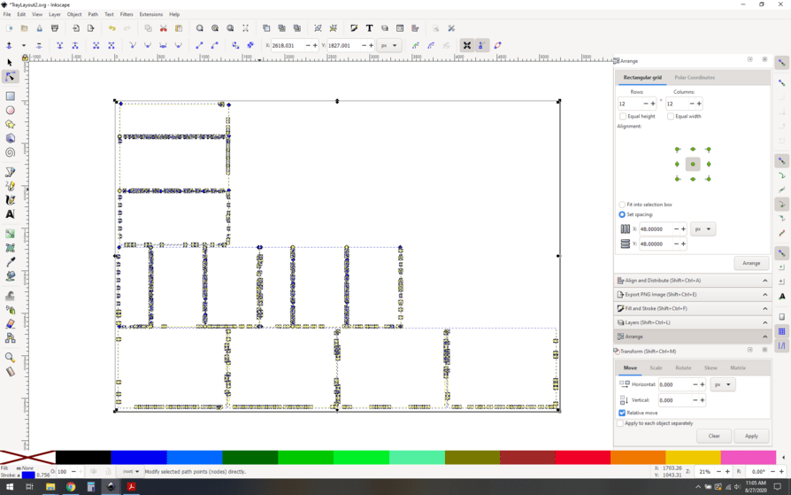
When I did Object to Path and then Edit Paths by Nodes (F2), I ended up with my vertical lines missing. I think the bottom line wasn’t missing because for some reason it was separate and I did not have the panel grouped (it’s something strange with the generated .output).
I have included an image. of the results I got. I can’t tell if your results had vertical lines or not.
Your problem is that the festi results are not actual objects, but a series of unattached lines, To use boolean techniques you need all the lines attached end to end. I have done this but it takes either dreary one link at a time connecting, or a study of exactly what Inkscape decides when you hand it a ton of such lines but once you have a fillable area only then will it do a decent job of booleans,
Between CMAdok’s post and this one, I think I understand. I was able to edit/add the nodes and delete the top portion of one of the panels without using the Difference operator. Tomorrow when I am fresh, I will complete the work.
Is there a different box generator that is better suited to using Difference on? Are Adobe’s tools able to handle Boolean operations easier? I am currently using Linux but ready to switch back to windows.
I use Inkscape to generate boxes now from scratch. I make a small rectangle and array it, combine those and they are the teeth that I can boolean copies to big rectangles that are the box parts. Festi is good for conceptualizing what you want, but once you understand that it is just as easy to build from scratch as fix a festi design.
I am not getting the same results. What do you mean by DI’d the link? Do I need to select or click on an item? The icon you are pointing to for ‘Make one or more consecutive nodes’ is ‘Join’ and not ‘Insert New’. This is correct? I am reading and learning as we go, and getting confused in new ways. 8).
OK so @rbtdanforth is right, the problem is your nodes not being connected by festi. The loops are a red herring, they’re weird but they aren’t causing your problem.
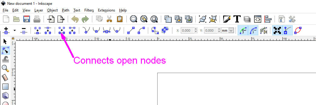
The reason I’m chiming in is that this is a simple thing to fix with the correct techniques. There are a couple of shortcuts that will help you out.
First things first, how to recognize your problem?
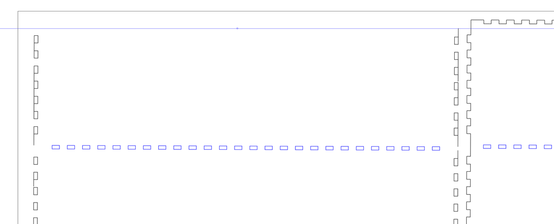
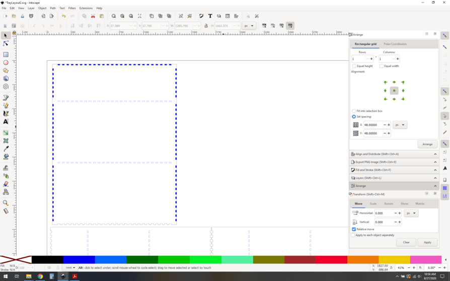
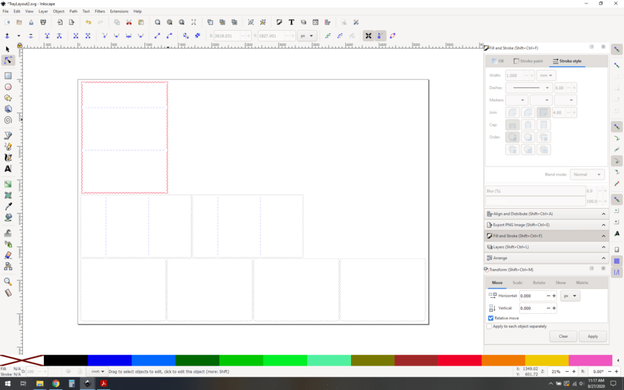
I like to try to fill shapes from generators, to be sure they look even remotely like they’re supposed to. To do that you have to select the outline of your box and apply a fill. You have an issue in that your parts are grouped, which adds a little complexity to selecting them. The fastest way is to select all and ungroup (control-shft-g) a few times, until it no longer says any groups are selected at the bottom of your screen. Let’s go with that.
Now that you have nothing but path objects selected, try just selecting the one outline you want to deal with. Apply a fill to it, and you see:
Very much not what you’re looking for. The solution is to join the nodes, but luckily this isn’t tedious or slow. This is going to be a problem with your whole document. Let’s talk about two ways to do it all in one shot.
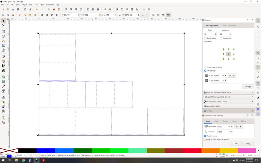
Select all, you’ll see every single path is highlighted.
Let’s say you really like your groups and want to preserve them. One of the nice aspects of the node tool is that it ignores groups and will let you reach in and select individual paths (@rbtdanforth will probably point out that control-click works too, which it does, but I prefer the node tool because it highlights the specific path I hover over, helps me be precise when selecting)
This will highlight all of your paths without breaking the groups. Now you can join the nodes as before, and you’ll end up with nicely groups paths that have all their nodes properly joined to make solid shapes.
–
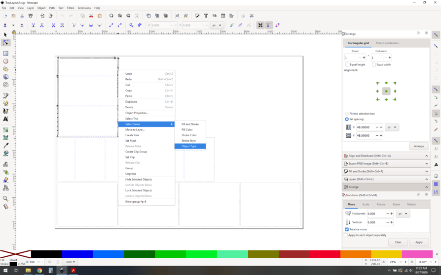
There are caveats, of course. This technique might not work for every situation. You may find that select same object type is too broad and selects too much, I tend to use stroke color instead for that reason. In this case, where your document is quite simple and (believe it or not) clean to start with, this is a quick and dirty way to get things done. How quick? Let’s time it if I’m not writing it up:
18 seconds. Starting by opening the document, then node selecting the box, selecting same object type and joining the nodes. I did say quick and dirty
The link I downloaded was @bwente 's and @evansd2 is way complicated. If you can and have dual screens you can load up all the floating windows there and not only have the commands easily available but see what is going on as well.
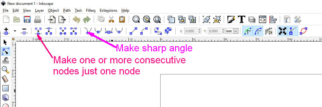
If you were able to do that you would see that all the groups were per piece and no reason to ungroup them. Instead, selecting all the nodes and hit the commands noted, and all the near points are joined. That little loop is the line leaving the node at an odd angle. By double-clicking the other command noted, every node becomes a simple corner and the loops vanish, Hit combine once or twice, it all becomes the single object. That is all that is needed.
Disagree, my way is not complicated. It’s a few simple commands, and solves the entire document’s problems. Your method requires analysis of which nodes need to be joined, path by path.
I’m simply doing what you’re advocating to all the paths at the same time. No need to wrangle each path separately.
I use this way all the time. Though I’ve usually been able to get away with selecting all the nodes in an object and hitting union. As long as they are all touching correctly, it usually puts all the paths where I need them. I’ll try join nodes next time.
@marks sorry, I wasn’t playing attention to the file itself so I didn’t notice that the nodes weren’t connected. I was just getting the difference to work.