Using the Passthrough with Illustrator (Beginner's version) 🤔

Notice to new owners looking for instructions on how to use the Passthrough:

Glowforge has now developed their Passthrough software and it is much easier to use than the method described below.

The link to the Glowforge tutorials for using their Pro Passthrough software can be found here:


Using the Passthrough with Illustrator (Beginner’s version) :thinking:

There is an excellent tutorial by johnse for using the Passthrough with Illustrator for more advanced Illustrator users here, if you don’t need a step by step walk through on it. This one is expanded for beginners.

Part One: Create your Design

1. Open a new file (20" x 12") in Illustrator.
2. Type the text really large in whichever font you want to use. (You can size it later.)

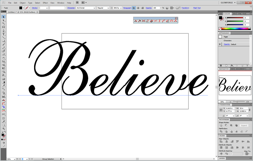
3. Select the text, Right click > Create Outlines.

In order to see what just happened, (because it’s going to look like nothing happened when you do that) , you can click on View > Outline . It shows the actual shape of the letters without displaying the Fill color. Fill color in text tends to obscure overlaps. The Fill is still there, you just don’t see it in Outline Mode.

And you get this:
See where the individual letters are not joined? They overlap each other and will cut as independent letters. They have to first be joined into one overall shape.

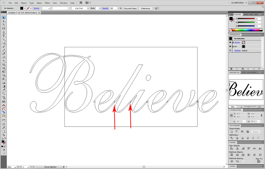
4. Those are grouped together, so right click and Ungroup . After Ungrouping, shift the letters over so that they overlap everywhere you want them to. (If they’re not joined together, you will get separate parts of the word.) You can use the Arrow Keys on the keyboard to nudge the letters over without them getting out of alignment.

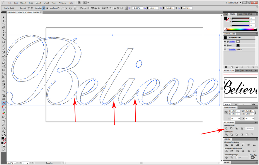
5. Now you want to join them, and since they are ungrouped, you can merge the shapes together. Select them and click on Unite in the Pathfinder palette.

You can see where the individual letters have joined into one shape.

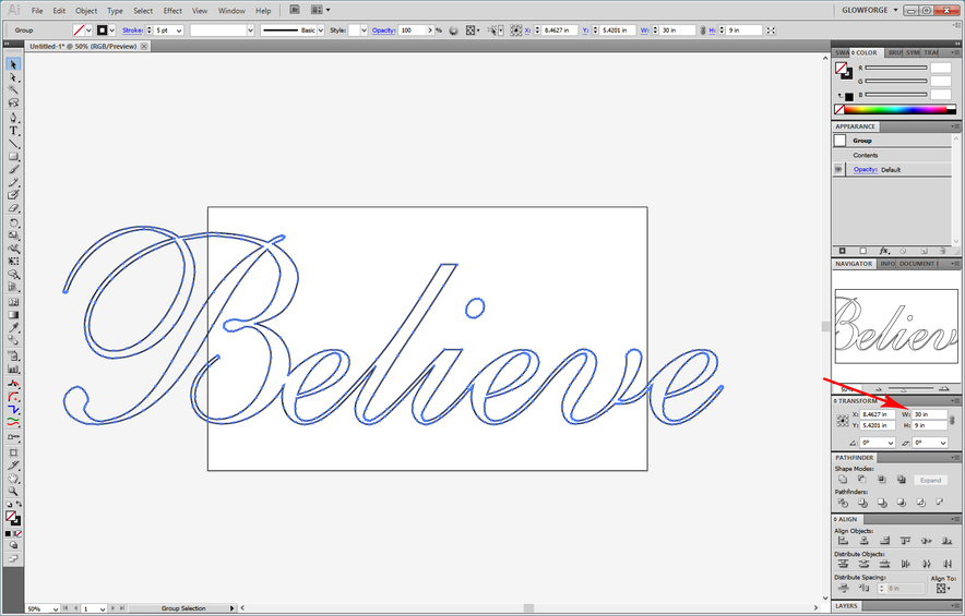
6. When you’re done merging the name together, you can go back to normal (View > Preview) viewing mode. You will see the shape looks exactly how you left it, but now it’s all one word. At this point, you need to set the Fill color to null , and give it a Stroke color . That’s how you set up a file to cut.

Part Two: Preparing the File for Passthrough work.

Now that you’ve joined everything together, you’re going to cut it apart. (Yeah, I know.) :smile: Each section has to feed in along the vertical measurement of the bed, so they need to be kept under 10 inches.

1. Scale your file so that the Word measures the correct size overall. In this case the desired overall dimension is 30" long, so select it, lock it to scale it equally if you want to , and set the measurement for the width to 30 inches in the Alignment palette.

Very important note: Make sure the height of your word overall is not larger than about 18 inches. You need a little bit of leeway for the marks and the jig alongside it. If necessary adjust the height down without impacting the width. (Cutting your material down to 20 inches or so helps a lot with alignment and pinning.)
2. Save a copy of your Word file.

3. Now you’re going to create a Passthrough Master File, so open another New File…again 12" x 20". Give it the name “Passthrough Master File”.

Part Three: Creating the Passthrough Master File.

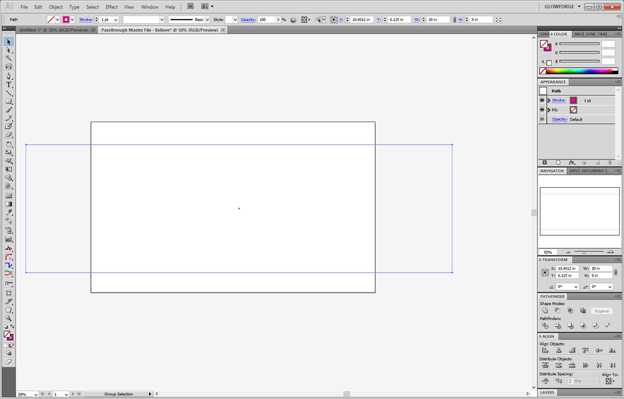
1 . Create a Guide for use in cutting up the word.

Drag out a red rectangle and set the size to be the width of your **word **…in this case 30 inches by 9 inches.

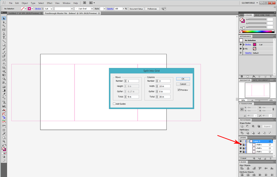
Split the guide using the Grid Function in the Object menu. For a thirty inch word, it can be split into 3 ten inch sections.

Select > Object > Path > Split into Grid.

Lock the rectangles in the Layers palette.

3 . Click on the tab for the file that holds the word, select it and copy it.
(CTRL/CMD+C.)

**4. ** Click on the tab for the Passthrough Master file and paste the word.
(CTRL/CMD+V.)

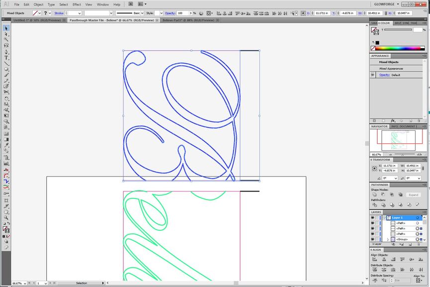
5. Align the word with the rectangles underneath.

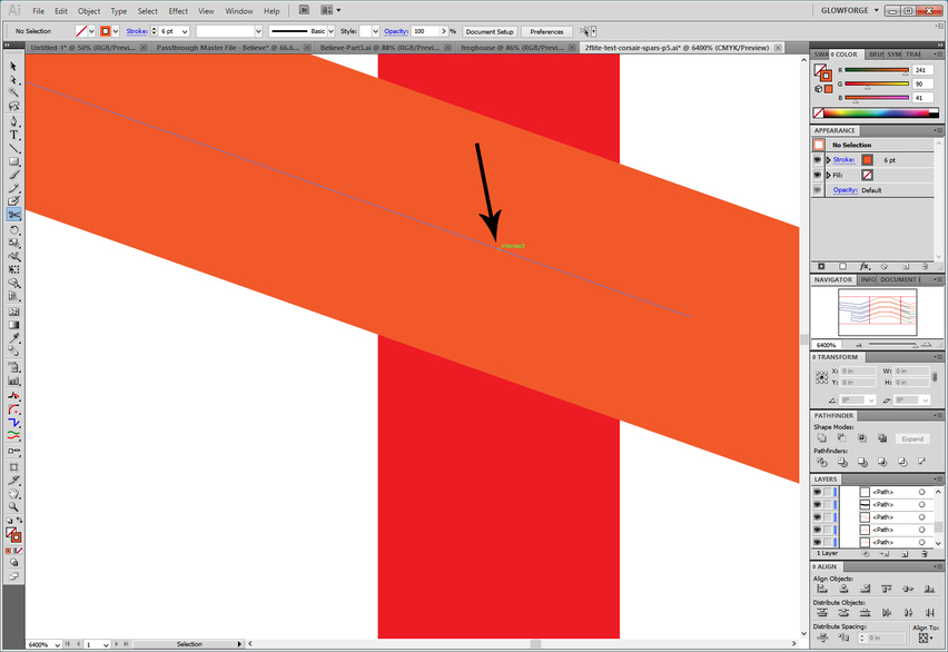
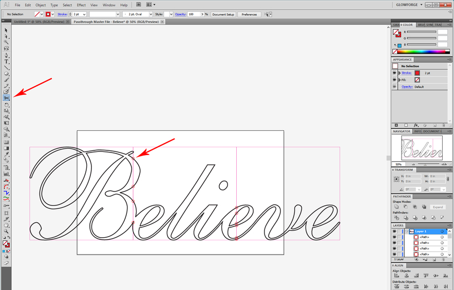
6. Cut the word every where the black word crosses a red line. Use the Scissors tool, and turn on Smart Guides to show the intersection for perfect cuts.

7 . After you have completely cut through the word paths at the grid lines, select it, right click and Ungroup . Right click again and Release Compound Path .

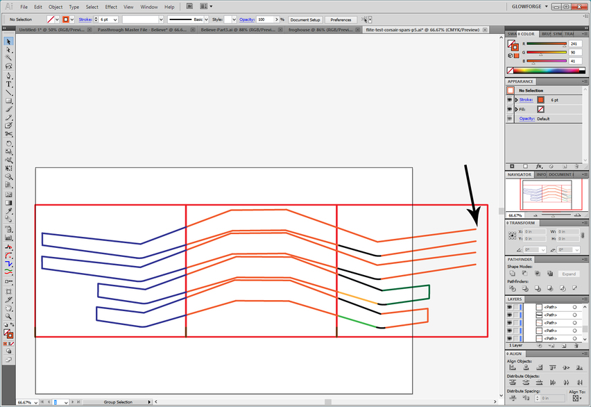
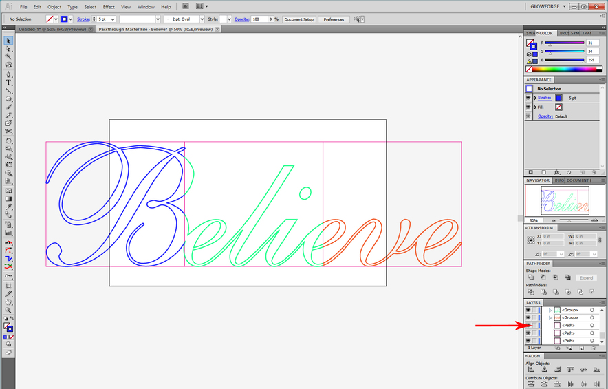
8. Select all of the path segments inside of a particular section and give it a different color Stroke. (Since the red grid lines in the bottom Layer are locked down, you can just drag across them to capture all of the segments inside each section.) The colors you choose do not matter, you just want each to be a different color.

9. Group Like colors together.
(Click on a colored line, click Select> Same > Stroke Color then CTRL+G to group.)
Unlock the Rectangles in the Layers palette.

10. Select each of the color groups and group it with it’s rectangle. (CTRL+G)

11. Rotate each color group and the red rectangle underneath it clockwise (-90°). (This is how the sections will feed into the machine, and you can see the bed size underneath the word below. Make sure it’s going to fit as it is processed through. If it’s too wide to fit, squish the width of the groups at this time.)

12. Create the indexing marks for the file.

Click the Pen Tool , use a Black Stroke color, and drag out a short horizontal line. Click first on the anchor at the top corner of one of the rectangles, then hold down the Shift key and click again out to the side to draw a horizontal line.

After you create the index line segment, copy it ( CTRL/CMD+C ) and paste it ( CTRL/CMD+V ) several times and anchor one mark at each corner of the rectangles on one side. (You can put them on either the left or the right side, depending on which side you prefer to anchor off of. I like to use the right side, more of the cutting area on the bed is displayed. Each of those marks should be spaced exactly 10 inches apart vertically, based on the original horizontal spacing for the word.)

  1. Save a copy of your Password Master File.

Part Four: Creating Passthrough Files.

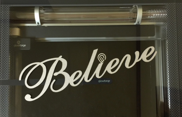
1. Create a New File. (20" x 12"). Name it " {Believe}_Part 1" .

2. In the Passthrough Master file, select all of the **Word ** segments for the first section, along with the two indexing marks for that section and copy it. ( CTRL/CMD+C .)

3. Click on the tab for the New File (Believe_Part_1) and paste that part into the new file.
(CTRL/CMD+V) .

  • Enter Isolation Mode by double clicking on the red rectangle, then click once more to select it. Delete the rectangle. Right click and Exit Isolation Mode .

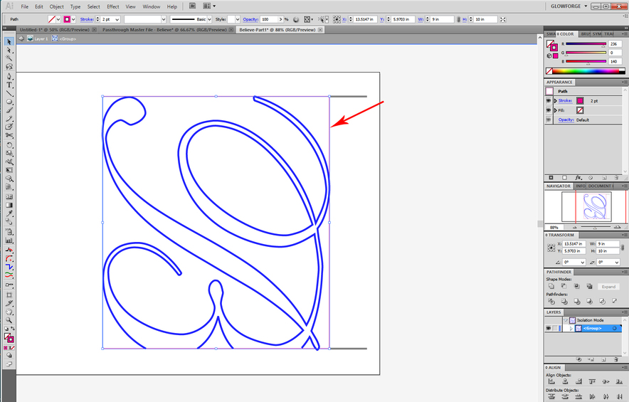
  • Select the word parts and the indexing marks and group them. (CTRL+G). Shift the group over close to the right side of the artboard. (If you are using right-sided indexing marks.)

4. Save the File.

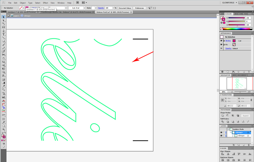
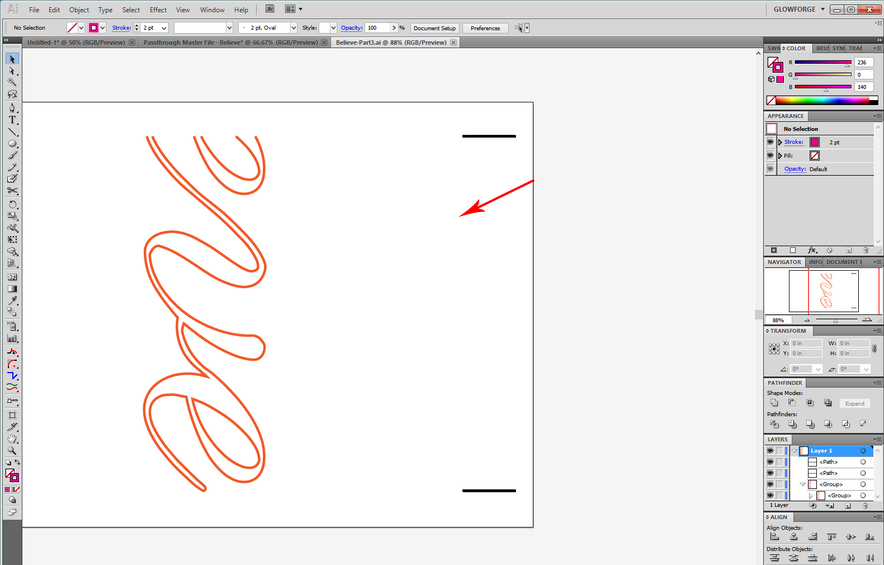
5. Repeat for the remaining sections.

Believe Part 2

Believe Part 3

Okay that creates the files you need. How you use them is…

Part Five: How to Use the Passthrough.

1. You print out a version of the Passthrough jigs here.
Either the left or right facing set, depending on which side you set the marks up on.
(Or you can print one of each and just hang on to them for the next project.)

2. You will need to anchor your tray in the machine. I like to use these boots. You can also just tape the tray into place with a couple of strips of Gorilla Tape. Just make sure the tray is level and don’t let it wiggle.

3. If you have not yet run the Improved Calibration program, GET IT, and run it. It helps to improve the overall alignment for the lid camera, particularly out at the edges of the bed.

4. You will tape one of the jigs flush against the side of your tray, so that it cannot move! You need to be able to see both sets of “marks” on the screen display, both the marks on the jig and the marks on the material, and they need to fall over the grid, so space it accordingly. You will probably have to insert it through the passthrough slot…just make sure it is flush against the tray edge. (And don’t forget to remove the rear passthrough cover before you get started.)

5. Then you load File 1.
(When you shift the files, you have to shift everything together so use CTRL+A to select everything, and just nudge it up or down using the arrow keys. DO NOT let the index marks shift relative to the other cut lines. If you have a problem doing this, draw a rectangle around both the marks and the cut lines, make that rectangle a different color, and then set it to Ignore in the Glowforge interface. It will force the parts to maintain relative distance, but you can and should completely ignore it in the file once you open it in the interface.) Try to position it on the screen so that the index mark falls close to the edge of the material. Use the Set Focus tool near the marks to improve the alignment accuracy. Align the entire design so that the index marks look like they are right next to the equivalent marks on the jig. (The 10" marks in this case.)

6. Lightly score the file index marks on the material without cutting anything yet. (Set all the Cuts to Ignore during this first part) . Adjust your design up or down and do another test score until the scored lines land right next to the 10" lines on the jig. (Walk over and look down at it to avoid parallax error, don’t rely on the screen view .) When it is exact, score it darkly again so you know which one it is.

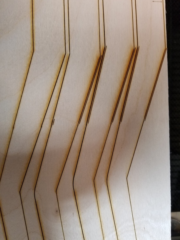
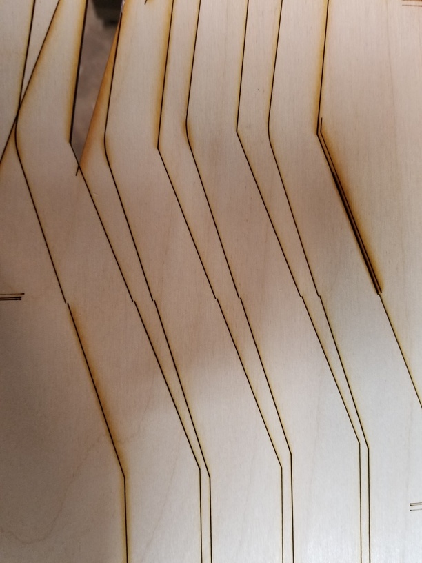
7. Cut Part 1. Be sure to check for complete cut through using a pick and without shifting the material - you don’t get a second chance. If it’s not completely cut through, send the cut a second time, without moving the material or the image on the screen.

8. After the cut is complete, shift your material forward until the bottom mark you scored on it lines up perfectly alongside the top 10" mark on the centering jig. Load the second file to the GFUI and place the top index line near the top 10" mark and the bottom index line near the bottom 10" mark.

9. Again lightly score the index lines and adjust the design until your top index mark score from File 2 lands right on top of the bottom mark scored in the first file. Once you have that adjusted, you can send the second section to cut. Walk over and look at it, don’t rely on the screen image, it is going to be offset.

10. Continue through each of the sections.

VERY IMPORTANT POINTS:

Make sure you have everything completely flush tight against the jig ruler the entire time - a tiny bit of skew is going to show up big time in the results. If your masking extends over the edge of the material, cut it off flush before you start. It’s enough to make a huge difference. You also have to keep the material as flat as possible on the bed…use pins wherever possible, and make sure you have the front and back of the material supported going into and out of the machine. Large sheets are going to bow if they’re not supported. That’s going to throw off alignment.

One other handy tip…keep a roll of masking tape handy to tape partial cuts to the backing material before shoving it through the rear slot. Otherwise the partial cuts will likely break and hang up from lack of support.

A smaller Glowforge version using the technique, cut from mat board:

Believe

Okay, that’s about it. Good luck. :wink:

34 Likes

Excellent tutorial and just exactly what was needed. Thanks!

4 Likes

Excellent tutorial! Between this and using snapmarks I can’t believe that Glowforge has not yet released any software to use the passthrough slot easily. It works, but not as advertised.

3 Likes

I’ve used the passthrough once on a project, my issue is slot height. There’s a LOT of stuff I want to run through it mainly for engraves, but can’t use it because my material is typically 3/4".

But GREAT tutorial!

4 Likes

Excellent and useful information presented clearly.

3 Likes

Awesome tutorial @Jules! Thanks for doing this writeup.

2 Likes

Wonderful tutorial. This will help so many with Illustrator, and even the process for other software.

2 Likes

My pleasure gang…this information was already out there, I just finally got it organized into somewhat semi-coherent order. (Which I’ve been meaning to do for a while.) We also have the writeup for the Inkscape Passthrough process if anyone is using that program, so we should be pretty well covered now. :slightly_smiling_face:

2 Likes

Your efforts do not go unnoticed! Thank you once again @Jules

1 Like

Snapmarks. What a nice idea that I never got to use.

We have to do this with the Snapmarks too. :slightly_smiling_face:

I know everyone who didn’t get to test them thinks that Snapmarks “hung the moon”. But even if you have them, you still need to understand this process for creating the files, so there’s no reason to wait around forever to use the passthrough. It’s why I posted this. I think folks might benefit by getting comfortable with the “cutting up the files” process, because we might still have to do that once the passthrough software is released.

The part that the Snapmarks eliminates is the need to be exceptionally careful to keep the material pressed up tight against the edge of the tray. And that’s about it. The marks you are creating in the file here serve the function of indexing marks, which is all that Snapmarks are.

Anyway, I’d like to encourage everyone to try it using this method a few times - just so you’ll be ahead of the game when the Passthrough software is released for the Pros.

1 Like

Jules, thank you for the fine tutorial. It was much easier to follow. I finally tried to cut a longer piece with the pass though slot. The item is a spar for a model airplane that I imported from a pdf. It is about 23" so I made a 24" box around the drawing and segmented into three pieces. The scissor tool added a node at the intersection, but it did not break the path, so I could not separate and color differently in the first drawing. I had to cut and paste the selected sections into separate files. I am a novice a illustrator, so I may have been doing someing wrong. I spent a lot of time getting the upper right corner at the same position on the 12x20 board. I eventually was able to get that corner within 0.002" for the three if the illustrator position readouts are correct. I was under the impression that when the drawing is at the same position when on the 20x12 board, it will be cut a the same location each time. I was able to get the alignment lines to lineup with the side scale in only a few attempts. However, when I cut the second part, the location was correct on the side scale but the lines did not match left to right.


I stopped the cut and nudged a couple of steps to the right. The end result is is reasonable.
The third cut did not go as well. It was too far to the left so I stopped the cut and nudged up one and to the right two steps.

The end result is serviceable, but not what I call accurate. If I had some vertical alignment scores, it could be tested before cutting. I had checked that the arm carrying the laser optics is square with the side rails a few months ago. I did the camera calibration this past weekend. Do you have any suggestions on how to get better results?

It’s hard to tell without seeing the file…you might have had some trouble with the initial Illustrator setup of the files…it’s very important to follow the instructions in that order so that the rectangles wind up underneath the pasted copy of the word on top. Otherwise you might place the cut on the rectangle instead of the word path. You also need to Ungroup the parts once you’ve made the cuts.

That part is important because the rectangles and the parts of the design on top of it have to stay perfectly placed relative to each other once you start copying it into the new individual files.

Did you cut the boot stabilizers and lock the tray down? (That can help to align the tray perfectly square.) It’s also critical that the material is pressed tightly against the side as it’s fed through…looks like the variation was on the horizontal axis, so it might have shifted a little and you might not have noticed. (It’s pretty easy to do, I’ve done it many a time.)

It actually looks pretty good for a first pass, and you managed to make some adjustments to it to correct it, but you shouldn’t have to do that if it works the way it should. You might want to try a few practice runs on some cheaper material like cardboard or mat board to get comfortable with the way it works. (Mat board actually works a little better, cardboard can deform a little because it’s softer, but practice is going to help, because there’s a lot to remember.) :slightly_smiling_face:

1 Like

I did use the boot stabilizers. They work very well. I used magnets to hold the material against the guide. I think that a cut parallel to the index guide may not be perfectly parallel. This could lead to an offset. The rectangle layer is below the drawing layer so the line being cut is above the red rectangle. I uploaded the file. If you are able to please review for any deficiencies.
flite-test-corsair-spars-p5.ai (1.1 MB)

No magnets, use the Honeycomb pins or tape. (The head can interact with magnets if they are strong enough, and anything strong enough to hold down wood is strong enough.). I’ll take a quick look at the file later this morning when I get downstairs.

Okay, looking at the file, I see a couple of areas where there might have been some issues introduced, and it has to do with getting comfortable with Illustrator mainly, so that’s going to go better next time.

  1. First …looking at the overall file…it appears that you left off a couple of end cuts on the spars.

I’m mentioning it because if you were planning to just run that up all the way to the edge of the board, that’s not the best idea…it presumes that the end cut is perfectly square to the side cut on the sheet of material, and in my experience on non-PG material, that doesn’t always happen. It’s best to close the cuts to keep from introducing yet another squaring problem to work around. (On the other hand, if this was just an early version of the file and you added the cuts later, that’s fine.)

  1. Second …you want to make sure to print an indexing mark at the top and bottom of each section…the one on the far right doesn’t have a top mark. (Again, if you added it later, that’s fine.)
    The camera view out at the far edges of the bed always requires more compensation, so it’s a good idea to use Set Focus near the marks when you are positioning the design, and you need one at the top as well as the bottom when you are shifting everything up and down. (The scoring iterations correct for that anyway, but you need to correct for both, each time. It will require fewer iterations.)

  2. One complication is in the design itself, and it’s because the cuts are not at the intersection of the rectangles. (While theoretically, they don’t have to be exact, I usually find that hitting the intersection exactly helps a lot with the alignment, especially if you are using the jig. It’s just one less alignment issue to worry about.) The Smart Guides make it easy to cut them once and get a clean cut, so I’ll show how to use them below:

Click on View at the top and check Smart Guides to turn them on.
Click on the Scissors tool, Zoom in and hover the cursor along the top path. When the scissors is exactly over the intersection with the rectangle underneath, the word “intersect” will appear in tiny green letters. While that is showing, click once with the mouse, and the scissors will cut the top path exactly at the intersection.

The picture above is zoomed in a lot more than you’ll probably need, but it’s hard to get a screen capture of that word…it’s tiny. But there will be a lot of zooming in and out to move around, so plan on that.

Okay having said all of that, (which will make it easier overall on your next try), …I still think the reason that shifted over on the bed horizontally might have been the magnets, so try it without them next time. :slightly_smiling_face:

3 Likes

Thanks for spending so much time on the file I uploaded. Especially since the first two deficiencies that you see in your view are correct in my view! I must an older version of Illustrator, so that may account for the difference.
I may not have had the Smart Guides turned on when I did this iteration of the design as I did in others.
I think that I will remove all of the cut lines and add them back to start over. I am making these spars for someone else, but I really need to get proficient at getting this method of using the pass through slot working. We purchased the pro model for the auto pass through alignment feature, but I have not yet used our Glowforge for cutting long pieces. Doing the breaking apart of the design is getting faster, but it is still tedious in part due to my lack of experience with illustrator.
I usually use Inkscape running on Linux, but there are definite differences between the Linux and Windows versions so I have been following your tutorial for illustrator.

Thanks again for all of your efforts and contributions to the Glowforge Forum!

3 Likes

I use magnets recovered from hard disk drives.
When i decommission a hard disk drive, I disassemble them to recycle the metals, collect the magnets and make any remaining data unrecoverable.
The magnets for the galvanometer movement are designed to have a field on one side only.
They also have a metal piece on the back which can also be used
to apply pressure to the material.

1 Like

Good Morning @Jules. This is some great information and I really appreciate it. I was have been killing myself trying to get it to work. I feel like I am missing something maybe. Once I cut my image in half and have them overlap, it does not seem to keep the correct sizes. My cuts are still off. I went into Illustrator and move the top back up to line the images up, and they are off. Am I missing something? Any advice would be greatly appreciated.

This is a very difficult process to pull off manually now that the Glowforge Passthrough software is being Beta tested. I believe it has been re-opened for sign-up, and while it might take a while for them to get you access to it, it will be worth it. The Glowforge software does all of this for you so you don’t have to be so careful.

The sign up for the Beta testing is here…if you do sign up for it, make sure you have run the Calibration program first to calibrate your machine, and read the instructions for the Beta testing.

If you don’t choose to sign up to test the Passthrough software, or if they already have enough testers for it, all I can tell you is to be extremely careful with how you are cutting the sections and placing the indexing marks. Precision is key.

Oh…and if you are working on some SVG file that you purchased or downloaded that might have been created in some other program besides Illustrator, it WILL introduce sizing errors into the design. Each program has it’s own default export size settings, and they are not the same in Inkscape or Affinity Designer or Illustrator. That makes sizing errors with SVG file types very common. When in doubt, always copy the file contents into a new 20" x 12" file and work from that. Check that the size is accurate inside the design program of choice, then when you save the SVG file for use in the Glowforge it will come across as correctly sized.

That’s usually what causes size issues and it happens before you get the file into the Glowforge interface. :slightly_smiling_face: