the upload to trinket pros can be tricky but it does work in windows if you load the adafruit drivers and avoid usb 3.0. I upload a trinket on average twice a week. it gets worse if in trying, one crushed the existing bootloader. Then one has to jump through at least 7 flaming hoops of fire. When I hit that point (rarely), it is easier to chick the trinket vs fix.
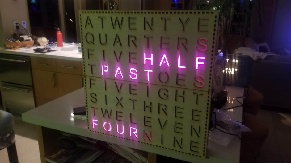
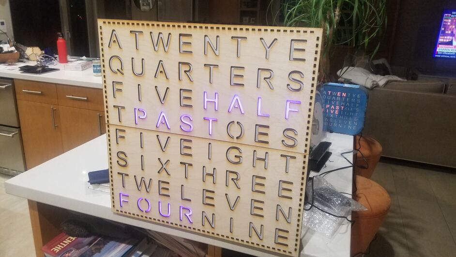
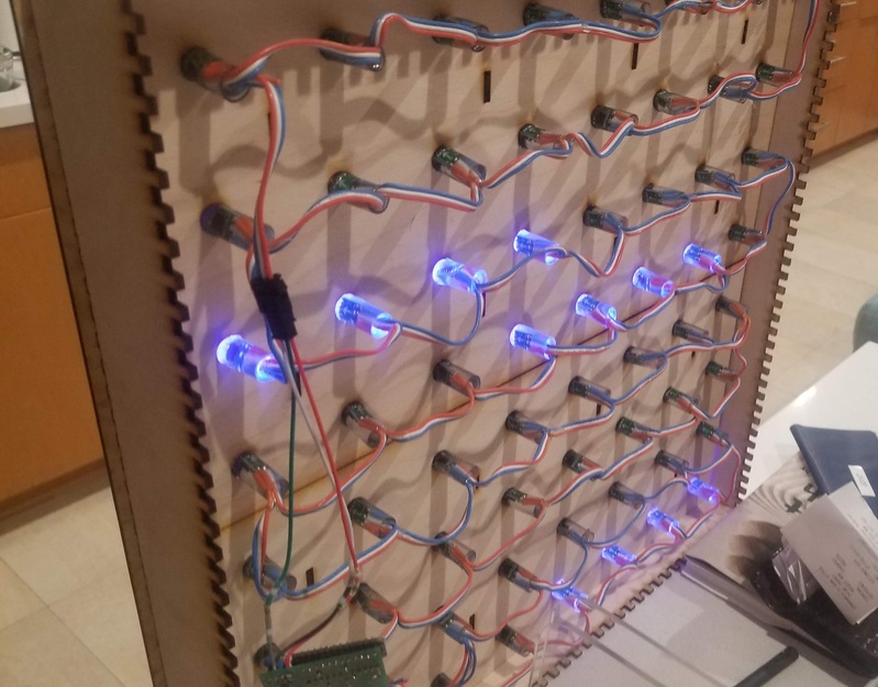
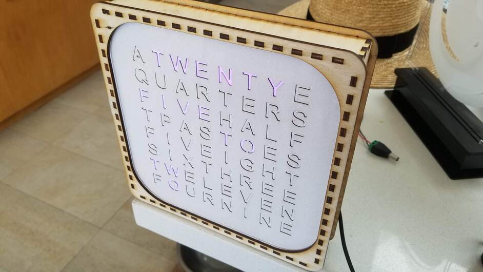
After making the small square “grid” version, then a big square grid version and several versions of e vertical and horizontal “list” models, I spent some time while on vacation to design a really big square/ grid design based on the max width of the forge. while the face could be done with a single piece and the pass through, for now (mostly due to the short term lack of a big enough piece of wood) I split it in 2 parts (i.e. the pass- through was not utilized). The rest of it was cut without using the pass through as well. I used a string of LED’s rather than a matrix and moved back to using 64 LEDs vs the 256 I used more recently on the “big” version.
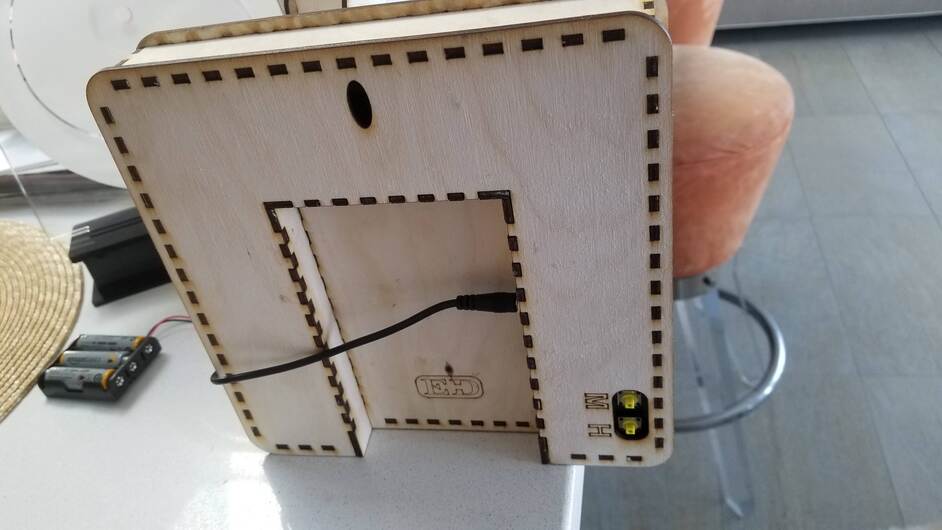
As first drafts go, I am happy enough. Still a bit o tweaking to be done (i.e. attaching the back and mounting the control board) The size is just under 19 x 19 inches. The string of LEDs is relatively cheap (about $16 worth of LEDs involved) That said, there is a lot more cutting time on the forge with this and more wood (1/8 Baltic birch plywood) in play. (10.5 sheets of 12 in x 20 in).
The new design is simple and eliminates the clear front and paper layer for the letters. IT retains a paper diffuse-er layer but this is cut by hand. Along the way, I had to update my clock circuit board as I had run out of the original batch. In that process I moved to a newer arduino (trinket M0) which meant that I had to sort out some issues related to the voltage mismatch between the led power (5 v) and arduino driver voltage ( 3 v) . I also had to tweak the code a bit but not too much.
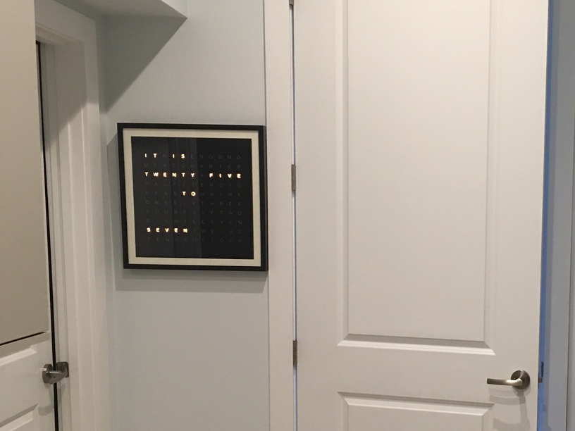
front shots, you can see an older model in the background.
Not for mine, unfortunately. 110 LEDs, and art modes that light them all up in saturated jewel tones, pulls up to 4 amps.
(You may know all that follows but it’s worth mentioning)
As for the rated voltages, I’d be careful. If you go that route I’d take a multimeter and check it before you connect it to anything. Sometimes you find that power supplies are pushing much higher voltage than advertised. If you’re using ws2812b leds for example, anything north of about 6.3v will kill them instantly. I once had a “5v” supply pushing 7.2, quality control at the cheap manufacturers is awful.
Also if you do go the usb route I wouldn’t try to power it from a usb connection through your micro controller — they typically can’t handle that much current. I’ve used a usb cable to power projects before but it’s a dedicated usb to 2.1 barrel jack which is then plugged into my project, the plug is wired to supply power to the microcontroller and leds in parallel, ensuring that the current for the leds doesn’t source from the controller.
Agree with what you shared. I have cooked a few of these LEDs myself. So checking the voltage before plugging in is key. I had a power supply that had been making 5.1 volts for a few years suddenly start putting out all sorts of higher spikes. Killed a lot of stuff in a short amount of time.
I am using only 64 LEDS on the bigger clocks so the current is not huge. I 256 LEDS on the ones based on the 16 x 16 matrix but drive those with reasonably low brightness.
I always keep the micro out of the led power path. I made a board to make all the connections simple. Power comes in, splits between the leds, micro, and RTC components. Includes conditioning resistor for the led data line and a big cap to protect the leds. I also included 2 small buttons when positioned properly, one can set the clock with them. Beats the heck out of hand wiring all of that.
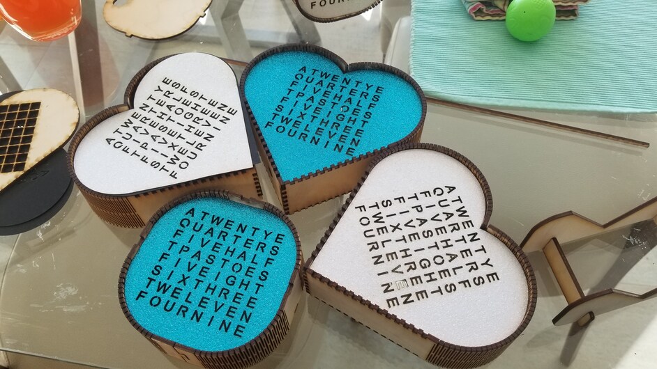
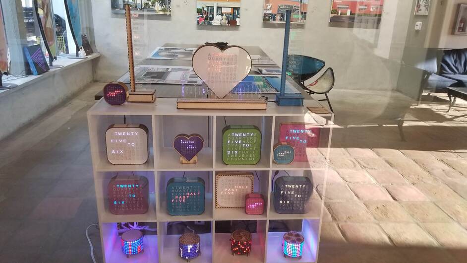
Made a few new versions over the weekend. A rounder small square and heart shaped clocks based on the 8 x 8 matrix (small) and the 16 x 16 matrix (large).
Shot of my clock collection from outside the gallery window today. 10 of 11 different (as in a different shape) designs visible. (the giant one is the 11th and is sitting in a different window).
Being new to this type of project (first one) I am assuming you took the clip off of the matrix with the set labeled 5v, GND, and DIN and used these three wires to solder into the Trinket? Thanks for the help and cool project.
i keep the input clip on the matrix. I trim off the power input wires and the output clip where they were soldered to the matrix. I attach the signal lead from the output clip to the output pin on the trinket. I attached the other 2 leads ( power and ground) to the 5 volt jack I use to bring power into the system. I used the now detached power input wires to connect this same jack to the trinket power and ground. thus, no new wires were needed and one can quickly attach or detach the trinket from the matrix ( which comes in handy). This keeps the trinket out of the power feed to the matrix which is a good thing.
The other reason to do it this way is that the solder on the matrix appears to need very high heat to melt. I avoid having to adjust my soldering iron by not soldering anything to the martix. thus, keeping my iron at a more reasonable temperature for work on the trinket. ( I solder often and a different temperature changes the feel and timing) Note: Use a 5 volt trinket you may have some signal issues (the matrix wants 5 volt logic).
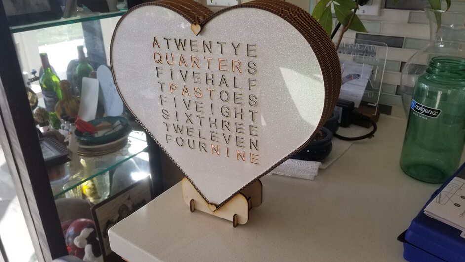
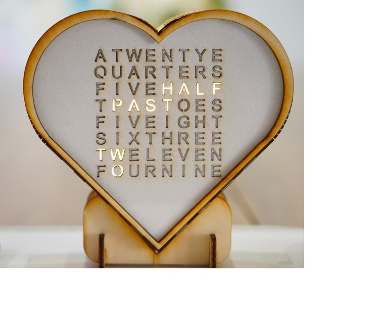
A nice photo by a local photographer Dana Rubin of one of these in a recent heart shaped design. This one uses the smaller 8 x 8 matrix although I did make a bigger one with the 16 x 16 matrix.