Bummer…yeah, OpenSCAD is a different puppy…seems to me it has one advantage in that it is a heck of a lot easier to just set up one formula that applies to the shape during the build, without all of the clicking we have to go through with other programs and since kerf is a variable - you can just change the value in one spot and everything adjusts automatically. (Like F360 does.)
But I don’t see a way around your wanting to post a different version for use in CAM applications, other than creating a copy of the file with kerf = 0, and then posting that one for CAM use.
Don’t know enough about how to use OpenSCAD to be able to tell you though.
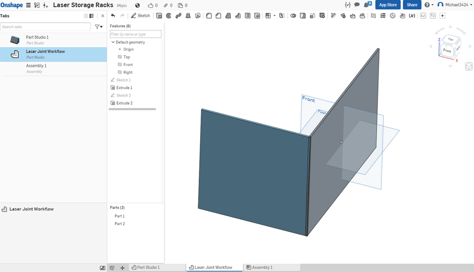
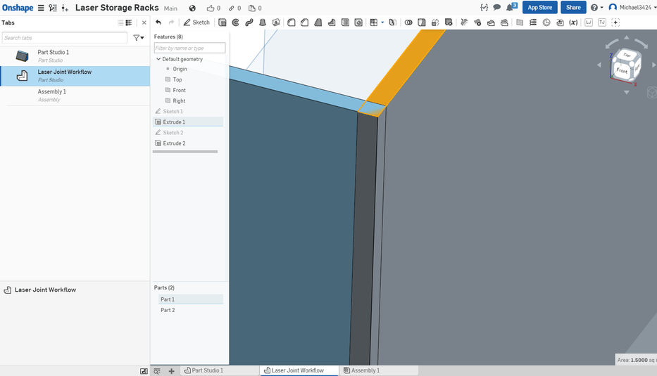
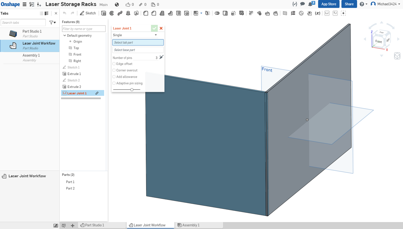
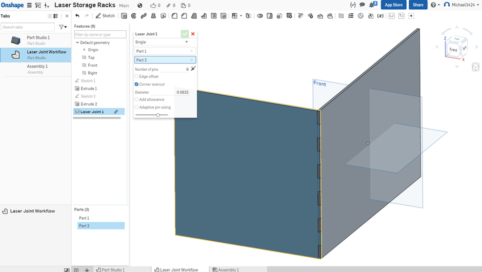
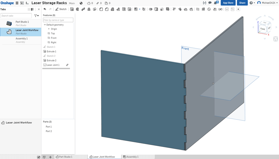
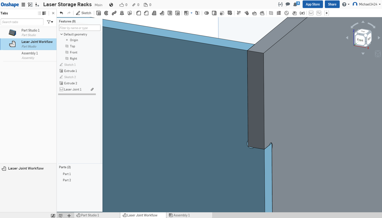
Sorry, I tried but just don’t have the patience or temperament for creating tutorials. I can show you the final couple of steps which may be of interest to some folks. The idea was to create two walls of a box, with one perpendicular to the other and to then create the pins (tabs) and slots that would form finger joints. The walls must be aligned so that their ends over lap each other and then the Laser Joint FeatureScript (created by one of the Onshape users) is invoked, and a series of entries are filled out in the subsequent dialog box to create the tabs and slots. The author has provided options for fit, and undercutting (so-called keyholes), among other features.
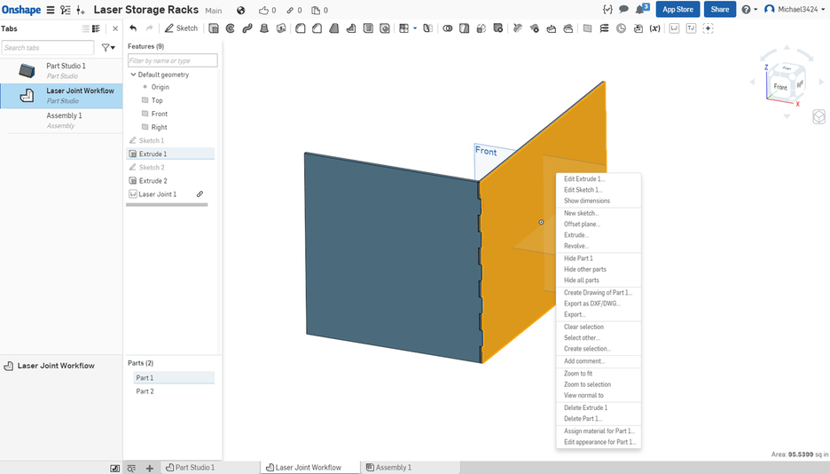
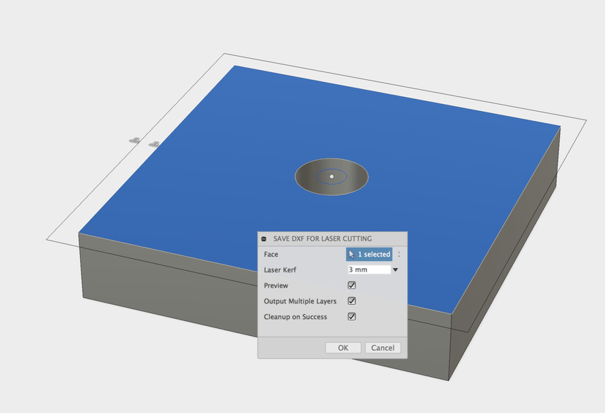
After the joints are formed by the FeatureScript you can select one of the wall faces, right click on it, and select “Export as DWG/DXF” from the drop down:
One could, of course, repeat the process for all six walls on an enclosed box. Actually doing the above took only a couple of minutes so it is really a quick process, much quicker than it takes to read.
Did I miss a step? After adding offset and exporting to dxf, my dxf has both the original path and the offset path. How do I suppress the original path?
I like your tutorials. Just a quick note that you don’t have to go back into the edit parameters box after noting the model dimension label to change it. Just double click the number and you can edit it to be “half” or whatever you named your user parameter.
Oh ho, look at this. You can actually export the toolpaths generated by Fusion 360 CAM directly as an SVG. That gets you all the little goodies, like kerf adjusted rounded corners.
Here’s how:
Go to http://cam.autodesk.com/posts/ and search for glowforge. Download the post processor file and save it as /Users/username/Autodesk/Fusion 360 CAM/Posts/glowforge.cps.
Change your workspace to CAM.
Use the Cutting tool.
a. Select tool. Add the one that looks like a laser. Change the type to Laser from Waterjet. Change the kerf width to 0.02 in, or whatever it should be. Change the nozzle clearance diameter to the same, or something small, while we’re here.
b. Select the face or contour you want to export.
c. In the “Passes” tab, set the Compensation Type as “In computer”. Also turn off “Lead In (Entry)” as it will be ignored anyway, and may generate a warning on some geometries.
There should now be a Setup in the browser. Use the Post Process action.
a. Find the Glowforge post processor under Personal Posts. Open up the Properties and have a look around. useColorMapping will use different colors for etching, but I don’t think that’s useful.
b. Hit OK. Files will be saved to /Users/username/Fusion 360 CAM/nc/ by default.
I couldn’t get the CAM export to work to save my life. But the DXF to laser plugin did the trick for my first project. Some day when I have infinite free time, I’ll try again with the CAM method as it should work better.
I was able to get an SVG out of the process, but it leaves a little bit to be desired. The corner kerfs aren’t properly attached to the other paths, so they show up in the UI as separate parts and have to be kept together when moved. It’s not ideal. Plus, the dimensions change almost randomly when going through editing programs. The plugin is indeed much easier.
One note: on Proofgrade materials, don’t perform kerf adjustment(?) I just cut a piece and the dimensions come out almost exactly as the designed dimensions.
Yeah, that’s pretty much the conclusion I’ve come to as well. I tried doing kerf adjusting on some early PG and wound up having to sand it because it was too tight to fit. (That was for the woods and plywoods, the acrylic can use a tiny kerf adjust to make the glueing less messy…tends to run all over the place.)