Continuing the discussion from Adjusting for Kerf in your Design Parametrically - Fusion 360:
This is a copy of info posted in the thread linked to above. The objective is to show how finger joint tabs and slots can be programmatically inserted into adjacent walls of a box designed with Onshape. The walls are created using standard Onshape features, positioned so that they overlap each other along one edge, and then an Onshape FeatureScript (called Laser Joint) is invoked to create the tabs and slots. FeatureScripts are user programmed macro-like utilities that can be included in any Onshape design to provide features that are not currently available in the official program. They can be written by Onshape employees or any user and are provided in either free or fee-based form.
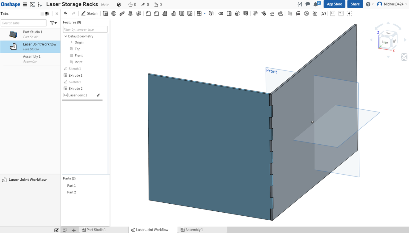
What follows is the final few steps of the process that creates the tabs and slots. Walls have already been created and positioned so that they are perpendicular to each other and overlapped on each other and the Laser Joint Featurescript. The walls must be aligned so that their ends over lap each other and then the Laser Joint FeatureScript (created by one of the Onshape users) is invoked, and a series of entries are filled out in the subsequent dialog box to create the tabs and slots. The Laser Joint author has provided options for fit, and undercutting (so-called keyholes), among other features.
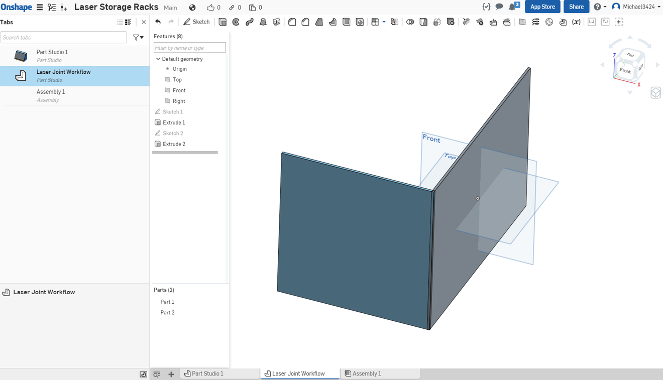
The walls before the FeatureScript is invoked:
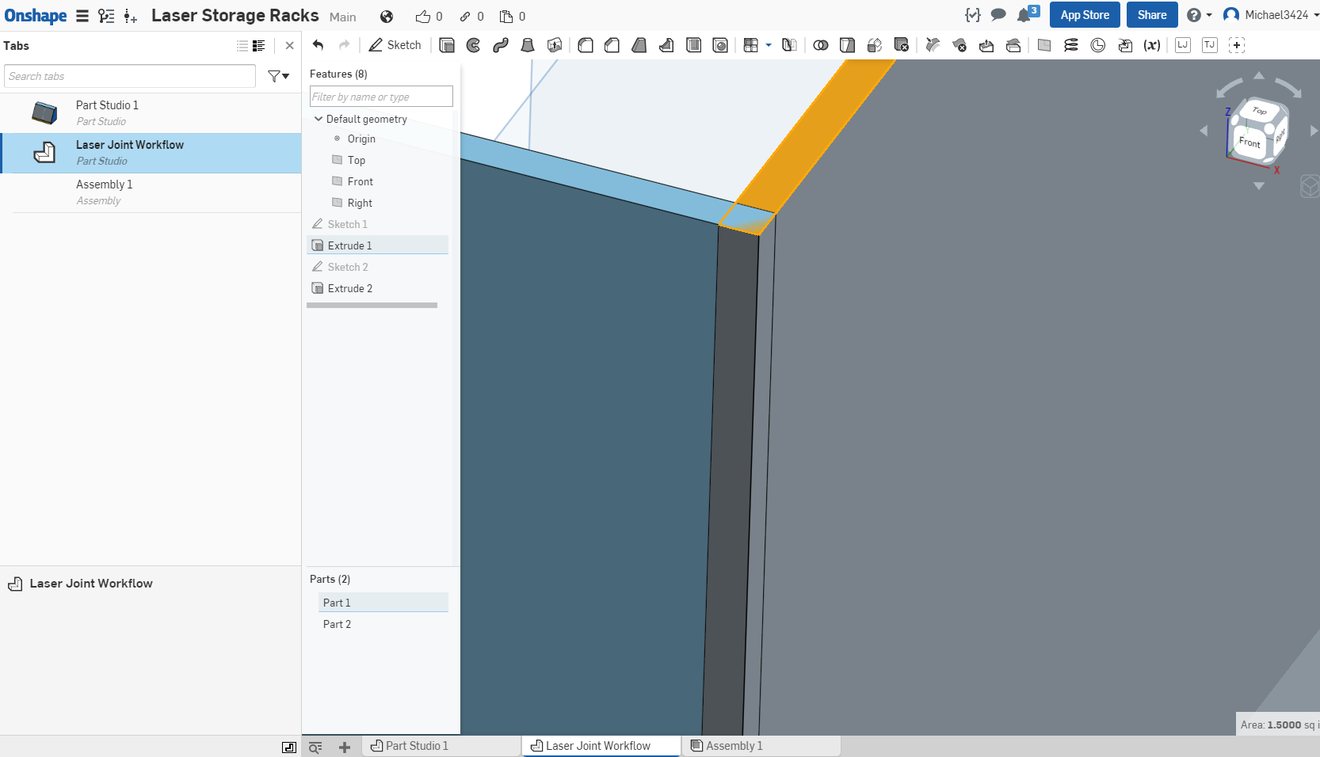
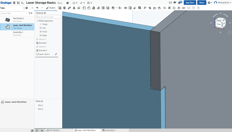
A closeup showing that the walls are overlapped:
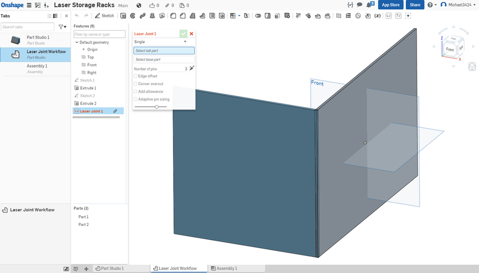
The Laser Joint FeatureScript has been invoked and its dialog box displayed for input:
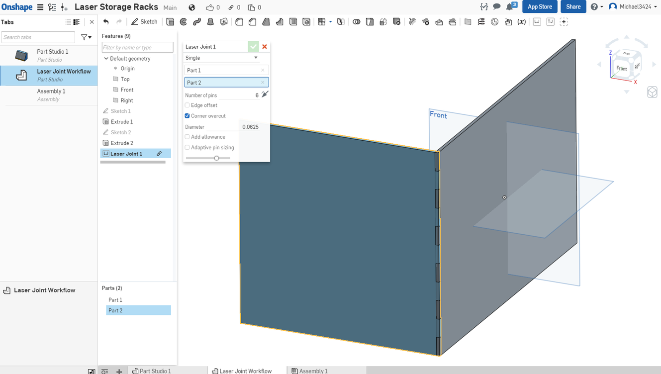
Result with dialog box filled out. I elected for a 1/16" overcut, which creates the clearance hole for the corners and for a perfect fit with no slop. Note that Part 1 in dialog box is one wall and Part 2 is the other wall.
The final result:
A close up of the top corner showing the overcuts in each joint:
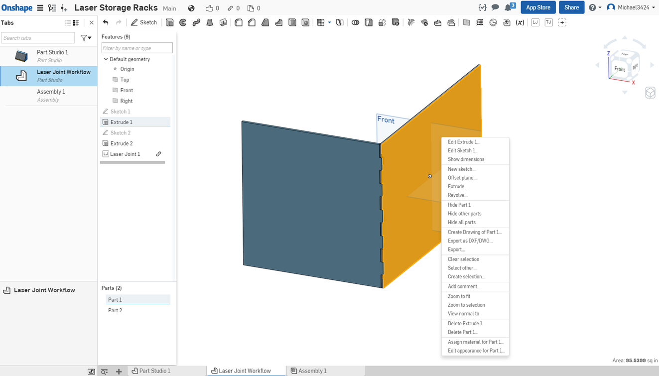
After the joints are formed by the FeatureScript you can select one of the wall faces, right click on it, and select “Export as DWG/DXF” from the drop down to save a DXF outline of the wall selected for cutting with your Glowforge.:
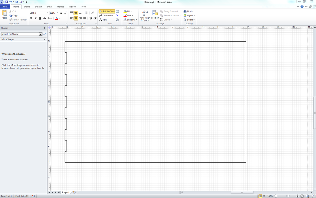
I don’t have my Glowforge yet so can actually try cutting a wall so I imported the resulting DXF into Visio just to verify that it looked OK. Until GF supports importing DXFs it will also be necessary to use a 3rd party utility or program to convert the DXF to the SVG file format that Glowforge understands.
One could, of course, repeat the process for all six walls on an enclosed box. Doing the above actually took only a couple of minutes so it is really a quick process, much quicker than it takes to read.
Onshape is a 3D parametric CAD program that (like Glowforge) runs in the cloud on my most browsers, including those in Windows, MacOS, Linux, Android phones, tablets, and Chromebooks, and Ipads and Iphones. It has a free, fully functional version that can be found here:
and they have a number of YouTube tutorials here:
as well as a very active user forum.

 (used to be able to have 10 private documents with limited space). Now they have it being unlimited public documents with unlimited public space. Guess I’ll have to switch over to Fusion360…little hesitant as it couldn’t even install without errors on my computer, but it looks like from other users it’s manageable. I do love my SolidWorks though at work!