I would like to see you try this with your printed axle design. I actually think it might work well, and could have less friction than wooden dowels. (Smaller contact area.)
Remember that your gears will want to be fixed to your axles, so that cross shape is actually an advantage.
True about the cross-axles, but I was hoping to reduce the pivot size. I would LOVE to use the cross-axles, but I feel like I would need to make the clock a lot larger to increase torque on the system. (Maybe I am wrong; again, this is all theory in my head right now, no experience yet.)
For my first attempt, I am playing with glueing some gears on some 1/8" dowels. I am planning on applying some beeswax or graphite in an attempt to reduce friction also.
They make bamboo skewers that are quite strong in the places needed and while not precise in diameter the total distance is tiny even if the percentage seems high, and the added strength more than makes up for it, coating with a film of UV or other hardener.
Just as @bill.m.davis, one of the projects I bought the was to make a wooden clock. I searched the net and found great resources like the ones mentioned above and the excellent book
I started building a prototype in MDF to learn the details, but soon discovered that humidiy and temperature warp the gears. I also had to adapt it for the brass rods and bearings I could get where I live.
I am redoing it in Acrylic which is much more stable. I will post some pictures soon.
Wow, pictures would be awesome! So you were able to successfully create the clock?
I cannot wait to hear more about what you learned (like the humidity experience) and see the pictures!
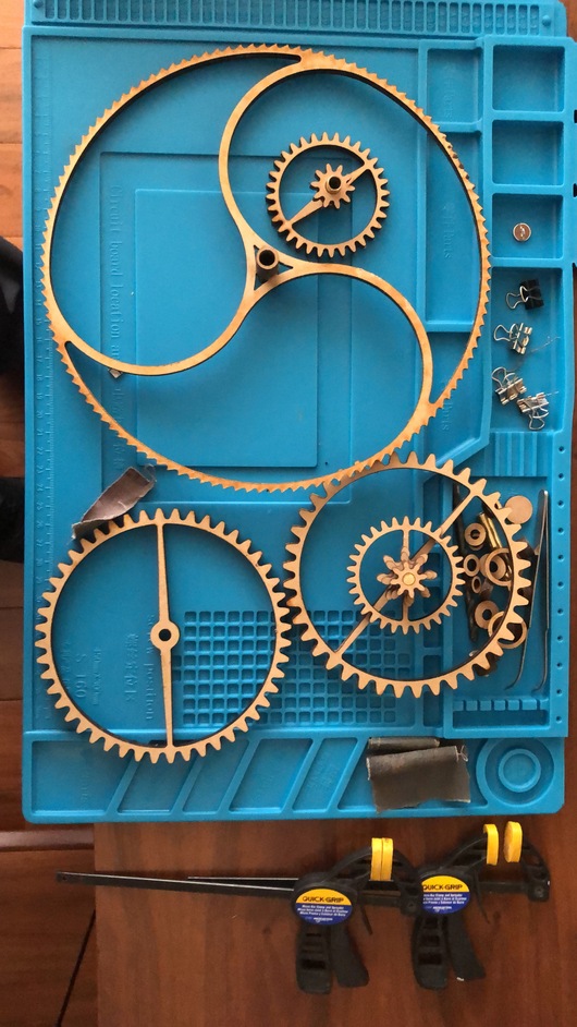
Here is a picture of the original parts in MDF and a short video of the mechanism in operation. I didn´t get to to cut the face and the hands because I realized that humidity and temperature changes warped the gears as made.
What is the “power” source and how long between “recharge”? I don’t see pulley/weight or a compartment big enough for a spring? Is it an electric motor limited by the pendulum?
I am REALLY intrigued now (I have so much to learn!)
Edit: After watching the video many times, it looks like the pendulum is the power source? I appears to be pushing what I thought was the escape wheel, but I do not recognize that escapement implementation… (well, time to go to bed for tonight anyway…)
After some more reading and research… I am thinking about gluing/pinning the wheel (large gear) and pinions (small gear) together and let them spin freely on the axle. This would reduce mass in the gear-chain, but it could increase friction surface…
I also read that the charred edge from a laser-cut hole can act like graphite, thus extra lubricant is not always necessary. But, I think I will still opt to use beeswax on my axle holes in the frame/gears.
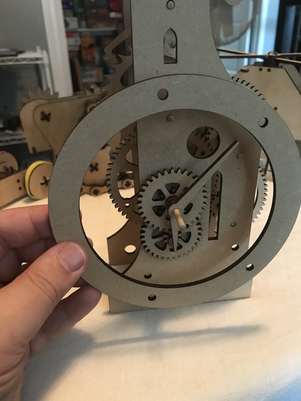
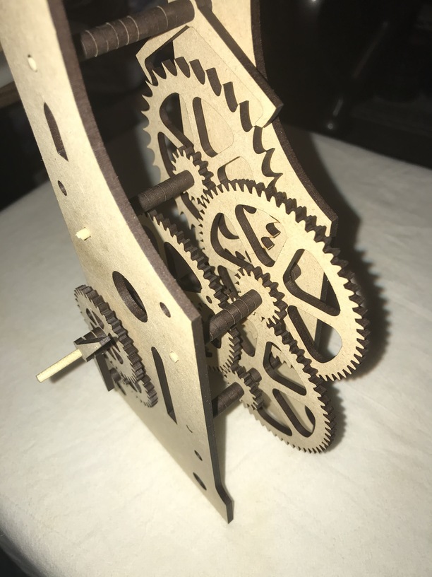
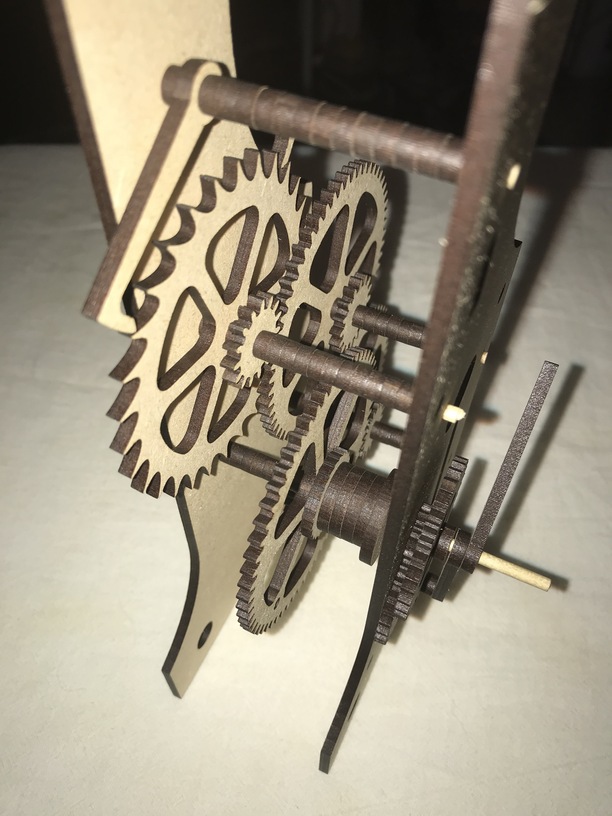
I call it a “model” because it is not a working clock. It is not even glued. I see several changes I want to make before I try to make a working clock.
I learned a lot just piecing this one together, and I would really like to try to use printed axles. I just hope I don’t make things more difficult for myself by eventually doing that… It will require my clock to be larger I think, but that will be fine.
While reading, I learned about a “springed pawl and ratchet” configuration for a one-way gear that looks amazing! I was trying to use a gravity-pawl-and-ratchet system that might still work, but there is elegance with the spring that I really want to try.
A spring-and-weight pendulum system is really intriguing also. I think that could be fun, but a normal pendulum seems like the best place for me to start with.
That is a really clever clock face design. If I am seeing that correctly, the input to the clock face is geared up for the minutes, and down for the hour?
I bet you could power that from the same type of motor you were trying to use on your marble run.
The minute hand is directly attached to the power-drive. Then the hour hand is attached to a gear that is geared down from the minute hand.
I would prefer the minute hand not directly attached to the power axle, so it could go longer without needing to be rewound. But, I don’t have much experience with this yet. So, I am just following different examples and looking at different clock designs.
Yes @eflyguy , I cut the main escapement gear, the pendulum and one of the minor gears, all from 1/4" clear acrylic. (Actually I repurposed an large office rug protector sheet which is all scratched from years of chair bearings rolling on it, so I turned it into “frosted” acrylic by passing a 800 grit sander).
The largest acrylic parts did indeed warp a little, enough to be noticeable when revolving around an axle, but I corrected the distortion with careful application of a heat gun and a some patience. However unlike the MDF conterparts, after being straightened, the acrylic gears have remained true and unaffected by ambient heat and humidity.
I have yet to experiment with plywood gears.
Also all shafts are polished brass and tubes, with bearings only for the pendulum.
Here is a short video of the hybrid MDF/Acrylic design.
I think this will be key when I try to make a working clock.
I think it will be fun to make one that can be completely cut from the , but I think that is less practical. And it would not hold up to wear-and-tear as well as a brass rod would.
I look forward to learning and experiencing so much more with clocks. This is such a fun space to work in! I think a clockwork structure that just continually moves will be fun even if it doesn’t keep time. (That is actually where most of the fun is, because you don’t have to worry about the timings and keeping them!)
Edit:@reynoso I just saw the video you added! That is so awesome looking! I still don’t see what keeps the pendulum from slowing down, unless it really is the power-source… I have so much to learn…
 was to make a wooden clock. I searched the net and found great resources like the ones mentioned above and the excellent book