That’s where I was going with the spacers, along with @henryhbk and his jig-grabber comment.
I know it would be an annoying bodge, but if you could fix something to the back and sides of the machine, and then in turn register the tray to that, would that be sufficient? The magnets thought was that magnets on the things affixed to back and sides could pull on the tray (or on something affixed to the tray legs) to ensure solid contact. So you’d be eliminating the uncertainty in the position of the tray.
That might be way overthinking things, and easier just to make something else that can be directly fixed with respect to the sidewalls/frame.
Oh… and to tie 90° stops in with the topic: in order to have a “0,0” origin point, you need to establish a grid, and stops that meet at 90° are a perfect starting point for a grid.
Adding the ability to move the 0,0 point would more accurately be called implementing a “work coordinate system”.
I’ve been told that the camera doesn’t move, but I can’t believe that. Everything moves (glass will deflect a fair amount). And when the camera moves, and the latent 0,0 point moves with it, any home-made stops attached to the side of the machine (or bottom or to the tray or whatever) will become inaccurate. The three-point fiducial jig proposed by Takitus (and others) might be our best hope.
I’m going to cut a 20x12 hole out of a bigger piece of plywood that I can place all the way to the back (with the hole lined up on the GF’s bed). I just have to see what I can place it against on the side that doesn’t move.
Making it is easy - draw a box around a 20x12 artboard and cut it - then you know it’s all in the right place and will be anytime you remove the piece and put it back. They can already replicate positioning using the artboard trick. But the GF can’t do that yet (I think it’s at 18 1/2x10 - I have to check). So I’ll cut the smaller hole and when the software catches up I’ll cut the bigger hole. Easy peasy
Modern machine vision can be precise enough to eliminate the need for any manual alignment. That is, once the camera positioning software is figured out. This is already used in production CNC environments, and it’s used in QA processes to quickly check dimensional accuracy of manufactured items.
This should be as simple as placing crop marks in the digital file, which most design programs already easily do for printer registration, and the laser cutter identifying an X and Y axis marked on the material (ie: use a pen and a square to mark directly onto the oddball scrap material) then the laser GUI automatically aligns the two using vision.
Well it should certainly work and the camera should find it easier to locate fiducials more accurately, but as I keep saying, if double sided cuts are to work then the camera should be able to find the corners of the work piece to sub kerf accuracy. So I don’t see why a jig is necessary. It was worrying that Dan liked it and IIRC put it in the hopper. It seems like he doesn’t have faith in the double side thing because if that is developed it is less work to reuse that software than it is to add fiducial finding.
Normal me accepts that as you have a glowforge and I do not there is a good probability I could be convinced you’re correct. Right now me is contemplating whether or not to try and antagonize you with argumentative posts until you do something along the lines of, “fine, send me your address and you’ll see for yourself.”
Good point. I’m very curious to see how they’re going to pull off two-sided cutting! And I agree, it seems like that framework could be used for single-sided jobs just as easily.
I do 2sided cuts/engraves on my CNC all the time using keying. I wouldn’t have a problem doing it here either, but if it’ll do it for me with good accuracy then I’m cool with that =)
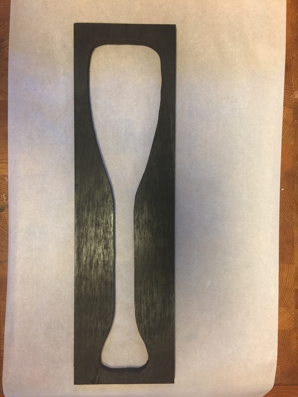
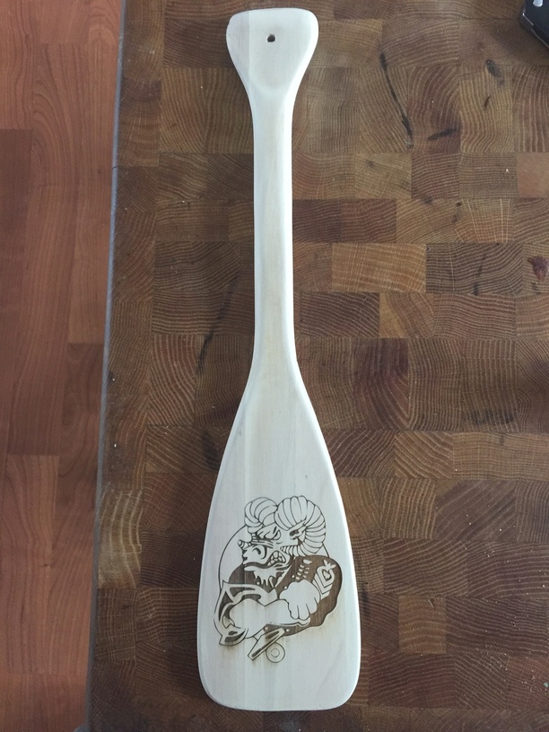
I utilize a similar function on the current laser I am using. I built a jig to hold the paddles I engrave. I then took a picture of the jig, pulled the phot of the jig into Inkscape and made an outline of it in SVG format and set it to the same dimension as the actual jig. I load it up in the laser program so that I can position what ever art I am using and it comes out perfect without having to figure out if I have it straight on the bed. It saves a lot of time and worry if I have it lined up correctly. Here is an image of the jig it is very simple:
And since the laser I work with initialized from the upper left corner of the bed all I have to do is place the jig in that corner place the paddles in it and no more worrying about grinding and sanding an engraving out of the wood to make it usable again!!
Those are ok, but I hesitate to even use those, as the spot size on red lasers generally tend to be rather large. They’re great when you don’t need a lot of accuracy, ya know making sure it’s actually on the object and not off to the side, but for anything with precision, math/numeric placement is your best friend.
I bet having one of those would be helpful, if it was setup right. One exactly like that, a crosshair, would need to be mounted directly above the 0,0 point since shining at an angle would cause the intersection to move depending on the thickness of the material it’s shining on. Of course, having the laser emitter mounted directly above the 0,0 point would obscure the cutting laser in that area. Two line emitters could draw a crosshair on the 0,0 point, and they’d only have to be mounted in such a way that the planes created are vertical and cross on the origin.
But even then, they have the problem mentioned above (large spot size). Though, even with a 2mm wide line, you could probably get down to ±1mm, which is… decent (IMO).
Right. Not much different than lining something up with the GF lid camera. No added value. Then you have the issue of trying to line up the red dot laser with the actual laser target on the material - they get out of alignment on the ones I’ve used.
It would be close, but the way the feet of the bed are designed, it still has a bit of play in it. Theres gonna need to be some additional guides built to make sure theres no shifting on the x axis. Some snug fitting L shaped pieces in the corners might work