Parallax on bed camera, how do i compensate for this?

Hi All,

I often engrave these 2 inch thick boxes on my chinese laser with no issue. One of the reasons i bought the GF is because of the ability to quickly sight and lay out designs using the camera. What i am finding though is if i use the camera to line things up its often off as much as 5mm in the direction of the cameras parallax being such a wide angle lens. Just wondering what people are doing to compensate for this. here is an image showing what i am talking about.

Others have suggested creating a cut out / template that can fit around something like this. Theu have suggested marking reference points on the "template and then using those to align in your design (with something that could be set to IGNORE. When i was working on my Escutcheon (USS Enterprise), I did something similar - I locked the acrylic down with push tabs, ran the cut, then removed the ship cutout, peeled the backing, and then re-ran just the engrave. Because it had a place to drop right back into, it allowed me to have the alignment tight. (Note: don’t restart your forge once you have aligned, though, as it could re-calibrate to a slightly different location.

Hope this helps / make sense.

2 Likes

Then you are going to be disappointed, my friend. The camera geometry does not allow for the level of precision necessary to be able to use it for accurate placement. As you’ve observed, the effects of a very wide angle lens and short, short focal length mean there is significant displacement as a function of the height of each portion of the image and its distance from the lens.

The camera can only tell you if you’re anywhere close. Do some searching for “jig”. It is the only way to accurately locate an object in the cutting area. And this method doesn’t need the camera except for initial placement.

A few questions for you.

Are you doing this without the tray in? (I’m assuming yes.)
What is the height you are inputting for the material?
The way the GFUI fixes the parallax of the camera is by adjusting based on the material thickness you enter.

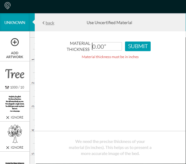
The problem is, the height is from the top of the tray. If you are not using the tray, you need to subtract the tray height from your thickness. My guess is your “effective thickness” will be 0.5". That should put you closer to the top surface and have less error.

@newbies_234 has made a good calculator for this.

3 Likes

Thats a good point Joe, The thickness i have been entering is the total thickness of the box which is 1.5 inches. Ill give it a try subtracting the thickness of the tray and see how that changes things.

@randy.cohen I am very familiar with Jigs but still find it cumbersome with the glowforge unlike my chinese x700 where i can manually position the head to a specific point to locate a jig or fixture which i cannot do on the GF.

1 Like

Oh, yes… In that case @joe’s suggestion is an excellent one. In your case, if they’re really 2.00", you’d very likely want to set it for 0.50". to get the best view. Let us know your result!

1 Like

Since this problem is being seen on materials that were purchased from another company, I’m going to move it to Beyond the Manual.