I think if you use the center coil (or the “fork” if you like) you can tell is the signals from one pair or another are earlier or later, which gives you a hemisphere to then use the 180 to derive a true 360 from.
Which reminds me, I need to get some italian bread and use up the rest of my sauce before it goes bad…
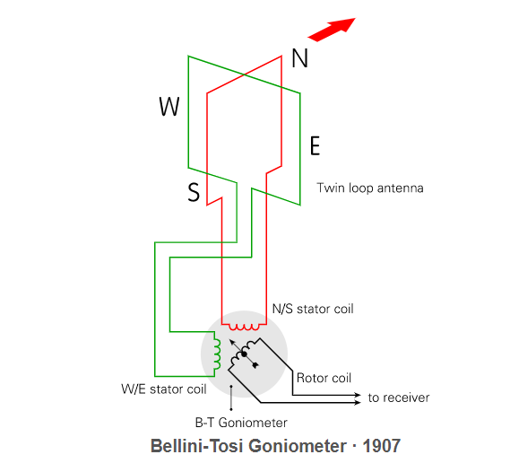
So I broke down and did some research. I’m no expert, but I’m not sure that schematic is consistent with a “Goniometer”. These types of devices are characterized by a fixed antenna array that’s connected to a set of coils that are remotely located. A detector coil is rotated within the remotely located coils, and the signal strength is detected there to determine direction as if the main antenna was what was being rotated. It’s basically the same idea as just rotating the antenna, without the bother of having to rotate something large. The radio in use in those days was mostly longwave, so the antennas would be 10s of feet in size.
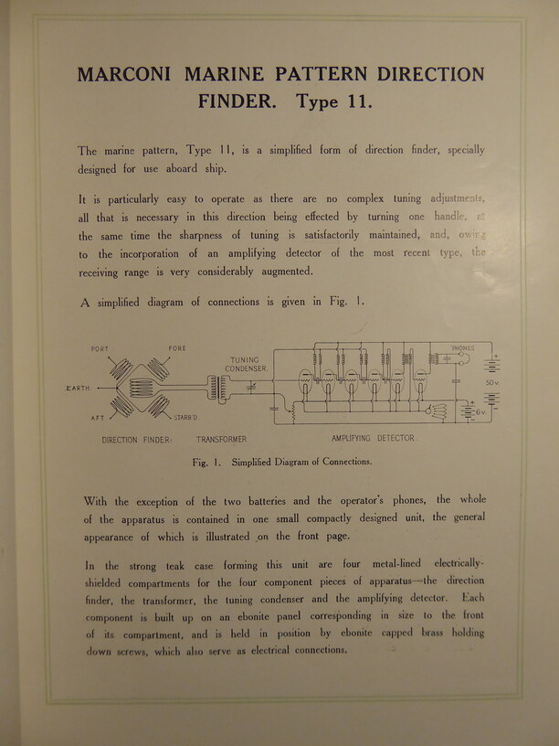
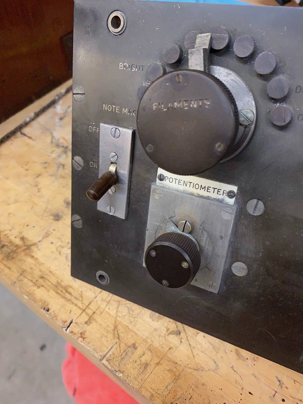
This below is a schematic of a Goniometer from the same era. The control panel at the top of this thread is more consistent with a device like what’s represented by this schematic. The schematic that’s attributed to the control panel shows a variable capacitor and a couple of potentiometers. But this Goniometer only has one big knob. The type of detector in the schematic above looks more like it’d be used for an “Adcock/Watson-Watt” direction finder. This system uses four antennas arranged with one at each corner and one in the center, and works as described by @johnj above. But it wasn’t patented until 1918.
Also, Vacuum tubes were still pretty new and rare technology in 1909. They were only invented in 1904. That schematic above uses 6 of them. It’s definitely for a RDF, but maybe not this one.
I did make an error on the date, I guess I wasn’t fully awake with I made that post. This particular version is ca 1916. We have another Marconi RDF at the Museum that is earlier. The schematic I provided is indeed for the unit pictured. The valves are Marconi V24 triodes, introduced in 1916. I’ve attached a page from the catalog below.
There is a pretty good Wikipedia article on these direction finders here.
I am a historian of early electrical and radio technology, so I have a pretty good library on this stuff. I’ve also written a couple of books if you’re interested.
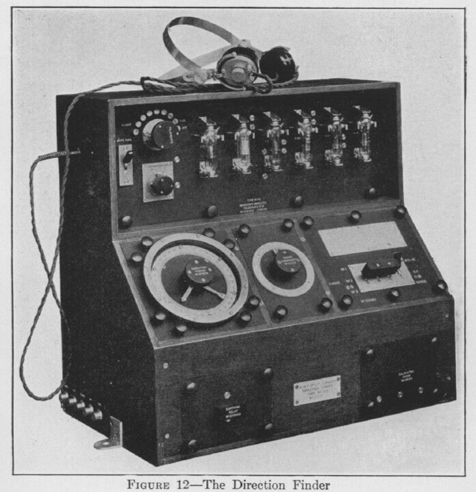
Edit: It just occurred to me you might like to see what the entire unit looks like. I’ll post a photo of the real thing once I’m finished with the restoration.
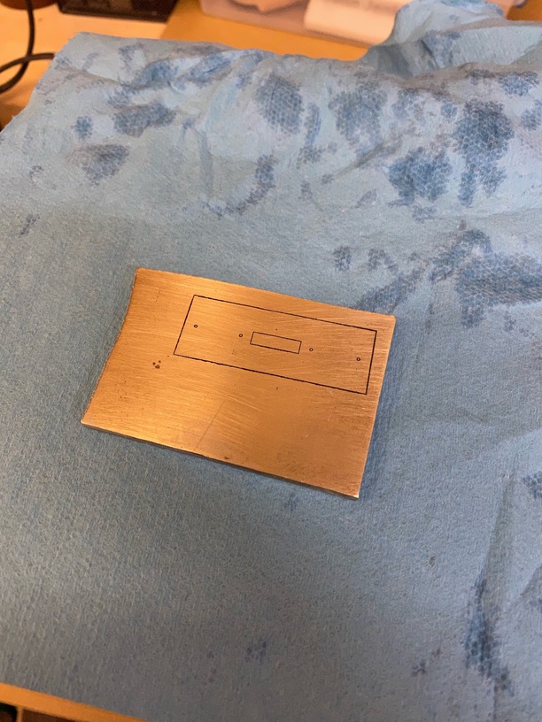
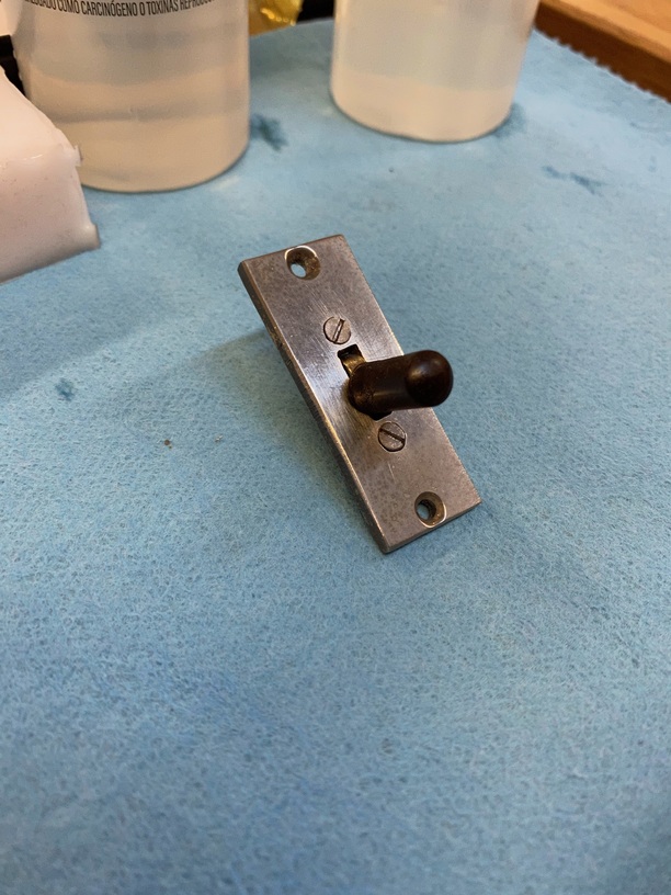
Just finished another part for the direction finder.
It’s true, you cant cut brass on a glowforge, but i can save myself a lot of time by marking the metal with the GF vs. using machinist’s dye & measuring/marking it all by hand. Here’s the process of making the switch.