Two questions

I don’t get how those settings work either. :slight_smile:

4 Likes

But according to @jamesdhatch that’s not true, right? white = white (always), but 0 = some level of gray (never white).

Well that speaks volumes. Perhaps somebody should be writing something up so we Muggles can properly take advantage of this mysterious set of features?

2 Likes

Really? The CEO, brand sponsor, puts out updates with no instructions and “wonders” how they work. Great job. Get an intern to start figuring it out and publish an official Glowforge manual.

2 Likes

What number is “white” in your system?

Not sure what you mean by “my system.” I’d always believed that white was 0. But now I come to find that’s not the case. It’s more like -1. Where 0 power gets applied seems to be somewhere around 254,254,254.

By “your system”, I meant the numbering system you had devised earlier in this topic. I think we are having a communication issue due to a differing mental model of how this works. I assumed that when you wrote those numbers down (0=5.0, 1=5.5, etc.) you were describing a mapping between levels of gray on the left to laser power on the right, and from the fact that the power level was increasing with the numbers, I derived that higher numbers are darker, therefore the scale starts at 0 with pure white and goes up to I-don’t-know-call-it-100 for pure black. Now you’re introducing negative numbers and triplets, and it’s starting to get really complicated.

So I propose an alternative view. I am a computer guy, so it’s more comfortable for me to use something closer to what’s actually going on. 8-bit grayscale is a thing, so we’ll go with that and keep it simple (so there are exceptions for what I’m going to say but we’ll ignore them). Each pixel is represented by a number from 0 to 255. 0 is completely black, 255 is completely white, and there’s a smooth ramp in between. Hopefully that’s pretty straightforward.

Now the question is how to convert those grayscale numbers into laser power. Let’s invent some terminology, which we’ll call “pews”. 0 pews is switched off completely (making no mark), and 100 pews full-on, making the darkest possible mark. Again, let’s ignore LPI, multiple passes, and the mysterious “full power” switch for the moment. A straightforward ramp from off to on, like a light dimmer.

Now here’s the model I have in my head for how this dialog works. I’m going to call the box at the top (Precision Power) “Power”, and the box at the bottom (Min Power) “Min”, to make it easier to say.

Glowforge

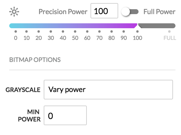
Simply, Power specifies the maximum pews, and Min specifies the minimum pews. The grayscale levels from your file are mapped linearly into this range, with the exception that pure white (255) is always 0 pews.

For example, as in the picture, where Power = 100 and Min = 0, the mapping is as follows. There will be a tiny bit of math here because we need to scale the gray range (0-255) to the pew range (0-100). Here is the formula: (255-Gray)*((Power-Min)/255)+Min. In this case, Power is 100 and Min is 0, so we’ll simplify it to (255-Gray)*(100/255).

Gray 0 (black)          -> 100.0 pews [math: (255-0)*(100/255)]
Gray 1 (almost black)   ->  99.6 pews [math: (255-1)*(100/255)]
Gray 2                  ->  99.2 pews [math: (255-2)*(100/255)]
[...]
Gray 128 (midpoint)     ->  49.8 pews [math: (255-128)*(100/255)]
[...]
Gray 254 (almost white) ->   0.4 pews [math: (255-254)*(100/255)]
Gray 255 (white)        ->     0 pews [no math, white is always ignored]

Hopefully by this point those numbers look sensible to you. Full black is full power laser, and full white is don’t fire the laser at all. In between, the darker the color, the more laser power.

Now what happens if we do something interesting, like keep Power at 100 but set Min to 10? Remember the formula: (255-Gray)*((Power-Min)/255)+Min. This becomes (255-Gray)*(90/255)+10, and our mapping changes as follows:

Gray 0 (black)          -> 100.0 pews [math: (255-0)*(90/255)+10]
Gray 1 (almost black)   ->  99.6 pews [math: (255-1)*(90/255)+10]
Gray 2                  ->  99.3 pews [math: (255-2)*(90/255)+10]
[...]
Gray 128 (midpoint)     ->  54.8 pews [math: (255-128)*(90/255)+10]
[...]
Gray 254 (almost white) ->  10.4 pews [math: (255-254)*(90/255)+10]
Gray 255 (white)        ->     0 pews [no math, white is always ignored]

Notice how everything is squeezed up just a bit so that it all falls between 10 and 100 pews, with a sudden jump at the end because of the “ignore white” rule. Mathematically, white would be 10, but the rule says we use white to represent transparency, and that overrides the minimum power calculation.

One last example, what happens if we change the Power setting? That controls the maximum power, and everything scales accordingly. To make the numbers more interesting, let’s say Power = 60 and Min = 50. Back to our old friend (255-Gray)*((Power-Min)/255)+Min, which becomes (255-Gray)*(10/255)+50. And the table:

Gray 0 (black)          ->  60.0 pews [math: (255-0)*(10/255)+50]
Gray 1 (almost black)   ->  60.0 pews [math: (255-1)*(10/255)+50]
Gray 2                  ->  59.9 pews [math: (255-2)*(10/255)+50]
[...]
Gray 128 (midpoint)     ->  55.0 pews [math: (255-128)*(10/255)+50]
[...]
Gray 254 (almost white) ->  50.0 pews [math: (255-254)*(10/255)+50]
Gray 255 (white)        ->     0 pews [no math, white is always ignored]

As before, we take the same range of source gray levels and now we squeeze them in between 50 and 60 pews, except it suddenly jumps from 50 to 0 when it hits white, because (say it with me) white represents transparent.

I’ve tried really hard to make this absolutely crystal clear. I hope I have had some level of success. If I have, the following should make sense:

If you crank up the contrast on your files so that they use all the gray levels from 0 to 255, as in the image I posted above, and you engrave with Min set to something higher than 0, there will be a jump from “almost white” to “white”, which might cause your resulting engrave to have what I’m calling “bald spots” in it. Areas where you expected “Min”, but got 0 instead. The workaround for this right now is to use your photo editor to remap the colors so there’s no 255 in the part you want engraved.

Some, but not all, file formats (like PNG and SVG) have extra information in them that makes it possible to say that certain parts are actually transparent. Not “pretend white is transparent”, but “there’s nothing drawn here”. And this is why some of us are making the suggestion that there should be a checkbox to toggle whether white is treated as transparent or not. Because we can use transparent to mean transparent and don’t need the extra step to prevent Amy’s hat from disappearing.

I hope that covers everything on this subject.

7 Likes

I really appreciate your write-up. It’s exactly how I thought it should work. However, there are a couple of issues that I see, and please correct me if I’ve missed something.

  1. We know that Power goes from 0 to Full and Full>100.
  2. We know power is not linear.
  3. We know from @jamesdhatch that 0 does not represent white (255) but some level of gray. Let’s say 254. Which sets white apart. I guess -1 wasn’t the best. Let’s call it -∞.

Nice write up. Perhaps an additional graphic or two would add to clarity.

1 Like

Sure, and I was obviously showing a simplification, but it doesn’t change the concept. If you turn on “Full Power”, the top end goes higher. Call it 110 or something. Maybe there’s nothing between 100 and 110, it’s pretty easy to account for that either way.

Again, correct but irrelevant to the point I’m making. I’m not trying to describe exactly how the power is modulated. Without inside information or Glowforge publishing the curves, I can’t do that. This is a simplified model for the purpose of explaining what Precision Power and Min Power do, how they relate to the range of grayscale values in the source image, and how there’s special handling for white. The only thing that “power is not linear” changes about this is the shape of the ramp from min to max. That’s a whole separate discussion, and one I care a lot less about.

I’m having a lot of trouble parsing this. My best guess at what you’re saying is that my scale is incorrect in the following way: since 255 has been stolen away from us to represent transparent, everything should be shifted down such that 254 is the whitest white and not, as I wrote, “Gray 254 (almost white)”. That’s a valid, but different interpretation of the words. I was referring specifically to the representation of 8-bit grayscale in the source file, independent of Glowforge’s mapping. In Photoshop or Illustrator or whatever, if you have an 8-bit grayscale image, 255 is white and 254 is very light gray.

You may have noted that in my formula, it’s effectively impossible to get exactly Min pews. Take the second example: I put 10 in the Min box, but the actual range is 100 down to 10.4. 255 gray would map to 10 pews, but the rule for “white is transparent” stomps on that value and clamps it to 0. So you can’t hit exactly 10 pews. As has been noted by experts in the field, there are three unsolved problems in computer science: naming things and off-by-one errors. Knowing how programmers think and how the code is likely to be implemented, I think my formula is probably close to the one used, and in the grand scheme of things it’s not important.

If that’s what you’re referring to, then there is of course a trivial change to make it work the way you’re describing. Perhaps the programmer who implemented this was thinking about it that way and came up with (254-Gray)*((Power-Min)/254)+Min instead. Table 2 would come out like this:

Gray 0 (black)          -> 100.0 pews [math: (254-0)*(90/254)+10]
Gray 1 (almost black)   ->  99.6 pews [math: (254-1)*(90/254)+10]
Gray 2                  ->  99.3 pews [math: (254-2)*(90/254)+10]
[...]
Gray 128 (midpoint)     ->  54.6 pews [math: (254-128)*(90/254)+10]
[...]
Gray 253 (almost white) ->  10.4 pews [math: (254-254)*(90/254)+10]
Gray 254 (white)        ->  10.0 pews [math: (254-254)*(90/254)+10]
Gray 255 (transparent)  ->     0 pews [no math, white is always ignored]

It’s a very subtle difference. In fact, it’s so subtle that Table 3 doesn’t even change, if you keep it to one decimal place. (You can do your own math now, I’m tired.)

If there was some other point you were making, it’s lost on me.

Let’s not. I deliberately kept my examples to the actual numbers used in the computer. There are no negatives or infinities in either the PNG-8 scale or the Glowforge pew scale. The way I choose to represent white is by saying “off”, “ignored”, or “0 pews”, which all mean the same thing. No angry pixies come out of the laser when your file is white (255) because (all together now) white represents transparent.

1 Like

So I think we’re really on the same page. Perhaps different paragraphs, but the same page. And that’s good enough for me! :slight_smile:

But regarding the 0 = white. In reality it’s 0 pews. But according to the Glowforge scale, white is not represented at all. It’s not in the scale. It’s not in the 0-Full range. In the actual Glowforge scale, 0 = ~254 (light gray) and Full represents Black (0), with 253-1 throughout the rest of the scale. What makes this significant is that if I change min, I’m not affecting white. White will always be white because it’s outside of the scale. It will never get even slightly darker no matter how I affect the scale. And this is not how typical design/editing software works. So it’s not intuitive.

I think any further quibbling over whether “white is outside the scale” or “white = 0, where 0 means laser off” is more philosophy than anything else. What you said there is what people need to know. And it’s much more concise than my attempt to settle the matter with charts and graphs. I’m not the first to make this mistake, I guess.

2 Likes

Didn’t mean to give that impression. Speaking from my side, I certainly wasn’t quibbling. Simply trying to ensure I have a firm grasp of what’s really happening. Because working with grayscale images for so many decades, this, like I said, just isn’t intuitive. At least not to me.

But I think you and I are, generally, in agreement as to how this works.

:roll_eyes: (look what I’ve gone and done now. And to think that I thought my questions were so innocently simple…)

2 Likes

We’re way beyond 10 answers, this is normal :smiley:

1 Like

How do we know this? Apart from discontinuity between 100 and full, I think 0-100 is probably linear. It is done with PWM. Not sure if the laser actually pulses on an off at 1.25kHz or if it is filtered to produce a varying analogue value to modulate the current.

It might not have a linear effect on the material but that will be material dependent.

2 Likes

If this is true, it would mean two things—both of which could be tested.

  1. Since the precision power range is meant to be the same on both Pro and Basic, it means that (at least on Pro) there is a significant power jump between black (0) and almost black (1) in your Model.
  2. Engravings would be very different on Pro vs Basic where full black was used.

I recall when they first debuted Precision power, the UI didn’t have the Full option, and the step from 99-100 was that large difference.

If you can select Full on the power setting for an engraving, then #2 is going to be the case—different results on Basic vs Pro. But I would still expect the pew values to ramp continuously without any big jumps, maybe from min pews to 110 pews…

But I don’t yet have a (working) laser, so my expectations are just guesses.

I recall this from previous posts on this forum.

Okay. Could be.

I’m so glad you asked this Xabbes! I have been trying to understand this “min power” thing for awhile. I just always leave it at 0 since we haven’t had any explanation of it from GF. (They really should explain these things.)

I read the first few comments and thought I understood and then the later posts got a bit deep :slight_smile: Can someone in the know confirm if this is still how it works? Is it true that white gets no power regardless and the lightest grey in the image gets whatever minimum power you set it to?

1 Like

I think the impression of non-linearity of the power ‘slider’ was due to the non-linear response of the material to the linear application of power. Back in June palmercr said he thought the power ‘slider’ was linear:

It seems the recently reverse-engineered puls file shows the ‘slider’ to be linear as well.

2 Likes

One thing to note here, if you look at proofgrade settings GF may not explain what these are or how to use them, but they use them in their settings, so we should likely experiment a bit more with them.

1 Like