It is disappointing hear that use of the camera has gone. Is there anywhere that states what functions have been dropped since I ordered it at the end of September?
Glowforge’s dual cameras measure the thickness of the material to a precision of four one thousandths of an inch.
Engrave complex, three dimensional curves with 1,000 DPI resolution.
Really, can it do that open loop without the use of the camera?
the Glowforge can measure the material thickness so 3D objects slide together perfectly.
Will it still do this? I took it mean I could design tab and slot 3D constructions and it would adjust the slots to account for the tabs being dependent on material thickness, which is not particularly accurate with acrylic.
I believe the cameras will still measure thickness, but it is before the cut that thickness is measured. The glowforge has little on-board processing. I believe the GF will still be able to do tab and slot designs this way (measure thickness pre-cut, adjust cut dimensions in the cloud, return to glowforge).
Good question. Nobody in the public has had a chance to look at the software side of things yet. Perhaps one can assign the tab to slot in the software? I do recall reading something @dan posted about the kerf thickness even being included in the slot (if my memory serves me correctly).
I think the only thing that has been removed from the capabilities list was the automatic characterization of materials. Meaning the GF can not easily automatically determine power and speed settings to get best effect for a particular material type. That capability was removed by the time pre-order began. The hi-res camera will still be used for all the other stuff. I’m sure a lot of those capabilities are still in development so don’t expect a demo anytime soon.
I believe that the camera is still an integral part of the glowforge’s operation. As rpegg stated, the auto-characterization was dropped before pre-orders. In my response, when I mentioned seeing features dropped they were always dropped in the proof-of-concept phase (when the auto-characterization went bye-bye) and not the verification phase (around pre-ordering.)
My openscad designs use material thickness and kerf input parameters in computing tabs/slots. Won’t know what is truly necessary until we see the interface, but it has been improving my geometry-math.
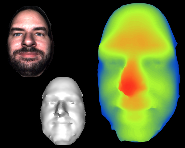
I asked about this previously, and @Dan has mentioned that the cameras can or will be used in concert gather depth information to a certain degree, a pseudo-3d scan if you will. How this will be used has yet to be stated. Here is the thread with that discussion:
If you are creating pockets, also be aware that the focal depth of the laser is limited, so you might get ~1.5" depth at the most. Still pretty cool if you ask me
I can understand your concern, and I see how the description as a 3D printer, combined with the use of the camera might have led you to expect something other than what it can do. But…
STL is a format that describes the surface of a fully 3 dimensional model as a set of triangular faces. This is not very useful in a situation where you have a beam if light that can only cut straight down, since you will never be able to cut concave sides, overhangs, or the bottom surface (well maybe if you flip it over). In any case STL is not good for all things, and it is not good at all in this context which is more 2.5D then 3D (no matter what the marketing copy says).
Yes but to design 2.5D objects you need to use a 3D package and they don’t generally output Z information in a grey scale format as far as I know. With 8 bit greyscale you would only be able to encode 1/4" at the claimed 1000 DPI resolution.
STL can represent lots of shapes that my 3D printers can’t print. It isn’t a problem as I design within the process limitations and don’t expect the printer to perform magic.
At the end of the day I could write a program to convert STL to greyscale if I have to. What is is more worrying though is I am beginning to doubt the 1000 DPI resolution. I suppose it might be the theoretical resolution but the accuracy is orders of magnitude less. Technically they are different things but when talking about printers with 1000DPI resolution you expect them to be able to resolve features on that scale.
I was really hoping that I could just make a 3D design and the GF software would (with a few more inputs - orientation, material type, etc) be able to do the Z approximations for me. I don’t mind doing the whole greyscale and assigning values thing, just would liked the GF software to do that part for me as I’m a complete laser amateur.
I guess I’ll have to wait and see the software.
@LindsayY Your expectations are understandable, considering that the device is being advertised as a 3D laser printer. This type of misconception is one of the biggest reasons why naming this laser cutter/engraver a “3D printer” was a poor marketing decision, in my opinion.
It’s not just the name, it is this claim on the front page:
3D high-res engraving
Engrave complex, three dimensional curves with 1,000 DPI resolution. To get perfect detail and sculpt with real depth, glowforge can carve away material with multiple passes, each one focusing more deeply than the last.
But your objection to 1000 DPI is conjecture at this point. Let’s be patient and see what it can do once it’s released in production. The rest of that statement seems to describe what the machine can do, although “three dimensional curves” should probably have been called “2.5-D surfaces.”
Im assuming that you are only referring to depth here. I dont see anything to say that it is not 1000 dpi on any of the axes. For the z being represented in a colorspace, it would only be limited in some of the 8 bit colorspaces (8 bit greyscale like you are mentioning). Bump it up to 16 bits and you have 65k shades of grey. That is more than enough to provide 1000dpi on the z-axis.
Again, none of us have seen the software, but I doubt theyd do all this work and then shortchange us on the z-axis stuff because they wanted to use an 8-bit colorspace. Even if they were technically stuck with 8-bit, you could still utilize the rest of the color spectrum for bit depth. Make a nice little rainbow painting… e.g:
Positioning precision to 0.001” (0.025mm)
Engraving at 1000 DPI with 256 power levels
Kerf is about 0.008 - 0.022 depending on material
So the resolution will depend on all three. Certainly not going to get a z axis any greater than 256 on a single pass without refocusing because the power level control is only that, and not going to get a 1000 dpi X/Y resolution because though the position accuracy is 1000 DPI the kerf (the width of material ablated) is wider. The spot size may be smaller but the material removed is larger. Still pretty darn good in all axes. Now keep in mind I am referring to deep cutting of material. Lightly engraving an image on material is a completely different thing and the resolution will be higher since we are not so much removing a kerf width of material as burning or discoloring the material with a small spot size.
Why would the power level have any bearing on the resolution of the z axis? @dan can you offer any insight as to what the z resolution is going to be and how you are going to map that to user input? Obviously an 8 bit greyscale map will limit it to 256 increments, and I am wondering if it will be mapped to 16 bit or a color depth map (anything greater than 256)
The tech specs state 256 power levels so while it is technically possible to do a mapping of color only 8 bit greyscale would seem necessary. I guess you could combine power and speed into one setting and map it to color, but to me that would be building a big technical wall to using it.
to add to the confusion. From the specs page focus depth is .5"
so that’s only 500 of the 1000dpi addressable along the Z access.
256 power levels is a major portion of that. More power faster/deeper burn to some degree is my understanding. More can be adjusted by number of passes, and amount of time the laser spends in one spot(speed). So I think 1000dpi is doable, but in the Z not obviously. And keep in mind just because you can accurately position the laser head to 1000 positions in an inch, the kerf will likely make a much larger mark.