Yep! 
We have to convert from 3D to 2D anyway…that is a tutorial!
(Specifically a tutorial on How to add an Undercut/Dogbone in OnShape.)
my tutorial moving instructions were wrong…just flat wrong…
Yep!
We have to convert from 3D to 2D anyway…that is a tutorial!
(Specifically a tutorial on How to add an Undercut/Dogbone in OnShape.)
my tutorial moving instructions were wrong…just flat wrong…
Ooh, need this function for Fusion 360!!!
Subbed
Did I miss a step? After adding offset and exporting to dxf, my dxf has both the original path and the offset path. How do I suppress the original path?
The sketch for the offset path needs to contain only the offset path.
The DXF export from Fusion360 will include the dashed construction lines as well so converting sketch lines to construction will not circumvent it.
I like your tutorials. Just a quick note that you don’t have to go back into the edit parameters box after noting the model dimension label to change it. Just double click the number and you can edit it to be “half” or whatever you named your user parameter.
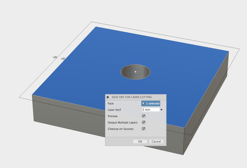
Also, I just came across this Fusion add on for DXF export for lasers with kerf adjustment.
This is what it does:
Select a face, it does the offsets for you and exports to DXF. The path outside the box and the small circle inside the hole are the cut paths.
Oh ho, look at this. You can actually export the toolpaths generated by Fusion 360 CAM directly as an SVG. That gets you all the little goodies, like kerf adjusted rounded corners.
Here’s how:
I couldn’t get the CAM export to work to save my life. But the DXF to laser plugin did the trick for my first project. Some day when I have infinite free time, I’ll try again with the CAM method as it should work better.
I was able to get an SVG out of the process, but it leaves a little bit to be desired. The corner kerfs aren’t properly attached to the other paths, so they show up in the UI as separate parts and have to be kept together when moved. It’s not ideal. Plus, the dimensions change almost randomly when going through editing programs. The plugin is indeed much easier.
One note: on Proofgrade materials, don’t perform kerf adjustment(?) I just cut a piece and the dimensions come out almost exactly as the designed dimensions.
Yeah, that’s pretty much the conclusion I’ve come to as well. I tried doing kerf adjusting on some early PG and wound up having to sand it because it was too tight to fit. (That was for the woods and plywoods, the acrylic can use a tiny kerf adjust to make the glueing less messy…tends to run all over the place.)
Yeah, I put in some ridiculous number like .008" just for press fit acrylic tabs. Better probably would have been to measure the thickness accurately.
0.008" (.2mm) is actually what I’ve read the kerf will be (in certain materials).
I’ve been waiting years for this moment: I finally did something that’s not ridiculous.
If cutting centerline, kerf as it applies to fit, would be approximately kerf/2, no?
You should do your own testing for kerf just to verify. The kerf on my machine is consistently smaller than the .008" that’s been mentioned before, and sometimes .004"
Snap fits might take a couple tries to get just right but if you try to adjust out 100% of the kerf, you still need at least a tiny clearance between parts (like .001" or .002") so they actually go together.
Sometimes the angled cut left by the laser is a help, sometimes it’s evil. Depending on the design, the tapered cut can make things easier to snap together. Other times if things are real tight, the angle will allow a snap fit in one direction but not the other so material orientation or even mirroring the artwork can have an impact.
I ran into this for the first time just yesterday. I was trying to snap together two small pieces of plywood and found they would fit together just fine from one side but not the other. Luckily it didn’t matter which side I used.
Kerf is the entire width of the cut line. When adjusting for it with an offset, you should offset by kerf/2. If you are measuring the width of, say, a fully cut out square, the half kerf would have been removed on both edges, so the kerf is the design width minus the measured width. Similarly, when working with designs where you are adjusting the full width (or diameter), adjust by the full kerf value.
Also note that the larger you adjust your kerf offset to, the tighter the fit will be, and the smaller, the looser.
I noticed that the Proofgrade settings put the focus at the top of the material. If you manual cut with focus at half of that, the angle should be symmetric top to bottom, no? I haven’t tried yet.
It seems that way from looking at the beam as an hourglass - moving the focal point into the middle would intuitively indicate that the narrow part moves inward. But no. That’s just where the highest power is concentrated but it still has to burn thru the whole thickness. You can get a decent visual using acrylic and trying to butt two pieces together.
Or at least that’s my experience.