I’ve had a Glowforge Pro since November 2020, and opted for the Premium option — and have read many helpful posts about nailing down where “zero, zero” is, given the parameters of the Glowforge lid camera. There are some of you, no doubt, who already know what I’m about to describe. But in short, I now know the maximum cut and engrave X, Y positions, and have jigs that identify a starting point for repetitive cuts and engraves (files attached). These jigs are removed before cutting or engraving as they rest on the side rails and will interfere with the laser arm travel. Here’s how I got there:
I created a new blank design into which I loaded eight squares — each 1” by 1”, using the “Insert shape (Premium)” function — though one could create them another way (Illustrator, Inkscape) and bring them into the GUI. As a retired cabinetmaker I revert to fractional measurements as a habit, but am becoming more comfortable with decimals as I make good use of the Glowforge “ruler” in the lower left corner of the GUI (which allows one to “Reposition and resize selected artwork”).
I picked an arbitrary Glowforge material and set things up so four of the squares would cut and four would engrave.
Then I went through the process of moving the “cut” squares outward and upward as far as I could and still have the GUI recognize them as “artwork” which would cut (just inside the infamous grayed-out, no-cut zones). Using the “ruler” I learned that the maximum “cut zone” corner measurements (positions) are:
Upper left position: 0.01 inch X, 0.01 inch Y
Upper right position: 19.49 inch X, 0.01 inch Y
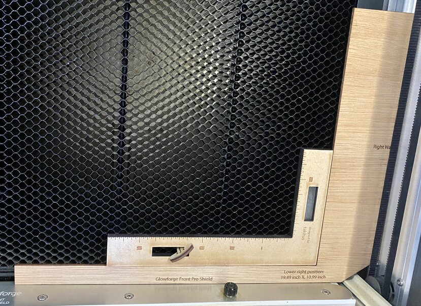
Lower right position: 19.49 inch X, 10.99 inch Y
Lower left position: 0.01 inch X, 10.99 inch Y
As an aside that also means the maximum cut area available in the GUI is 10.98 inches by 19.48 inches.
I repeated the same iterative process for the “engrave” squares and confirmed what I had earlier read in some of the community posts — the left-most and right-most maximums are a bit less than o objects set to “cut”, with a buffer that allows the head to slow down at the sides during high speed engraves. The maximum “engrave zone” corner measurements (positions) are:
Upper left position: 0.0247 inch X, 0.01 inch Y
Upper right position: 19.25 inch X, 0.01 inch Y
Lower right position: 19.25 inch X, 10.99 inch Y
Lower left position: 0.0247 inch X, 10.99 inch Y
You’ll note that all the “Y” positions are the same for both cutting and engraving.
Since most folks think, or define, “zero, zero” as being in the upper left corner (just as the GUI does) I thought I could make a positioning jig that would pinpoint position 0.01 inch X, 0.01 inch Y. But since the lid camera can’t be used, nor can the crumb tray (because it can move) I thought I could use the left and back sides of the Glowforge bed. So, I scored the upper left square on a piece of scrap and measured (carefully) the distance from the square’s scored left side to the left aluminum “wall” — above the crumb tray and just below the black belt, and from the square’s scored upper side to the back aluminum wall of the Glowforge bed. This measurement takes into account the Glowforge Back Pro Shield — so this measurement for a Basic or Plus Glowforge would be larger, I would think. I had to design the jig with notches for the left knob that holds the pass-through shield in place as well as the mechanism that travels on the left rail. After several attempts (with cardboard — always a good idea to start with cardboard) I had a jig that worked. But last night during a period of “lucid dreaming” it occurred to me that a jig using the lower right corner (position: 19.49 inch X, 10.99 inch Y) butting up against the right aluminum wall and front door would be easier to design as there are fewer interferences (although the front door of the Pro has a ~.145 inch thick front pro shield — so the jig for a Basic of Plus Glowforge would need to take that difference into account).
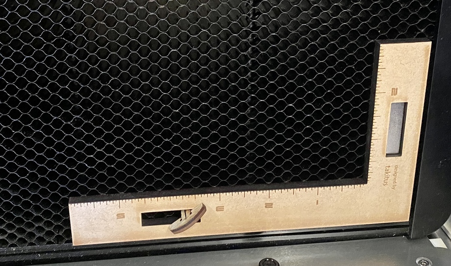
With these jigs in place one could then position the work material using another jig. For example, the fiducial ruler expertly designed by Takitus — which I have tweaked a bit. I made the two legs 1” wide and used ¼” thick MDF as ⅛” material slips beneath these jigs. I have rectangular magnets and cut shapes to accommodate them. And depending on your predilection regarding magnets or “eljefe4’s” honeycomb bed hold down pins — you can use either. Both are pictured. Or I imagine one can use any of a number of other jigs, or spacer material of known dimensions, or even using a tape measure to move the work material off the jig edges to a certain X, Y position.
This is by no means an end to the search for a perfect alignment — but an extension. Please chime in and make improvements (and post) as you see fit! Alignment Jig Files.zip (20.4 KB)
Keep in mind that the maximum size will change depending not only on the operation but also on the speed settings. This may affect both the left to right edges and front to back edges. I suspect that the actual zero may be in the center of the working area.
Also it’s worth mentioning that zero position is software-controlled, so it theoretically can change at any time. Glowforge could update your machine and all your work could be invalidated. Worst part is that you probably wouldn’t know until the job was blown and materials lost.
This is why I don’t invest much in trying to find a true absolute zero, but instead focus on finding relative zero at the time of the job. I really ought to write up my methods for efficient jig technique, but it’s a lot of work to document it, as @capnmike can attest.
What’s funny is that I do pretty much this - but I eyeball it because I don’t do anything that requires that kind of repeatability. If I leave ~1/4" on the right and the bottom I can use all the material for a cut - obviously it moves further in with speed or engraving, but I drop my material and the width of the t-pins is almost exactly the space I need to leave
Very Interesting. I wonder though, have you tried the glowforge re-alignment “tool”. It’s a special print operation that is similar to a printer’s test page to detect where items hit - note you will waste one-side of a piece of material, and they support only proof-grade, recommending the Draft Board. (But you can use the other side just fine and the other will just have a lot of glowforge symbols which looks ok for backs, etc).
I did this and the alignment is super close now. It is still off by a hair so I’m seeing how to do your suggestions to make it 100%, but was curious if you had tried that and what the results are to you. I think glowforge would be better if they had some auto alignment when composing designs. Too many times I place objects on a partially used board and they move when it re-aligns for print and I have to move them again.
Yep, I did the camera recalibration and got good results (well within Glowforge’s advertised tolerances). The jig, however, doesn’t rely on the lid camera, but on hard, unchanging reference points taken from the inside walls of the Glowforge.
Sorry – no video. Here’s how to use the jig for the lower, right corner of the bed (the process is the same for the upper, left corner of the bed jig): place the jig on the crumb tray so that the right side of the jig firmly touches the right-side aluminum rail (it will fit just below the bottom loop of the belt, and just above the protruding lip of the rail. And the bottom edge of the jig so it firmly touches the Front Pro Shield (which is part of the drop-down arm). The second picture in the post shows the jig “in position”. At this point the upper, inside corner of the jig is located at 19.49 inch X, 10.99 inch Y (and will always be as the jig is static and unchanging). Now you can position your work material on the bed distancing it up and away from that corner however you want. In that same second picture you will notice one way to do this using a fiducial ruler expertly designed by Takitus — which I have tweaked a bit – nested against the alignment jig and pinned in place by a honeycomb bed hold down pin (thanks to eljefe4) and a rectangular magnet. With the ruler (or any other off-distancing devices) in place – carefully remove the alignment jig (that’s what you see in the first picture – although in that first picture there is no work material on the bed). Close the lid, load your design and laser away. You can repeatedly change out work materials and the alignment (position) will not have changed (unless you inadvertently moved the off-distancing device), and you can move on to other projects and when it’s time to come back to the one that you’ve set up using this alignment jig --repeat the setup and (again) the upper, inside corner of the jig is located at 19.49 inch X, 10.99 inch Y (and will always be as the jig is static and unchanging). This is what allows for repeat cuts/engraves, not relying on the lid camera. I hope this explains the jig’s use.