Files are here:
jwalton - Heng Lamp.zip (31.8 KB)
This is going to be a long read. 
Mostly parts of the lamp are made up of a “stack” of parts - the corks, for example, are made of a set of rings labeled “C1”, “C2”, “C3”, etc… These parts stack on top of each other in order.
The files are named for the material they are supposed to be cut out of. Almost the whole lamp could be printed out of 5mm ply with very minimal changes; the middle of the lamp is made of two 6mm ribs on either side of a 3mm rib, for example, which is 15mm in total. You could swap these out for 5mm ply without changing anything. Most of the other parts could be done this way with minimal changes. (One day when we can upload designs to the catalog, maybe I’ll redesign this for all 5mm.)
Start with assembling the main hoop - find S-MID-1, and glue an L-MID-1 to either side of it. Same for S-MID2. You’ll notice S-MID2 and friends have a little notch in the top - this is there to hold the chain in place. Take one of the chain anchors, cut the ring off, put the anchor over the end of the chain, and put it in the notch, then fill the notch with JB Weld or a similar epoxy.
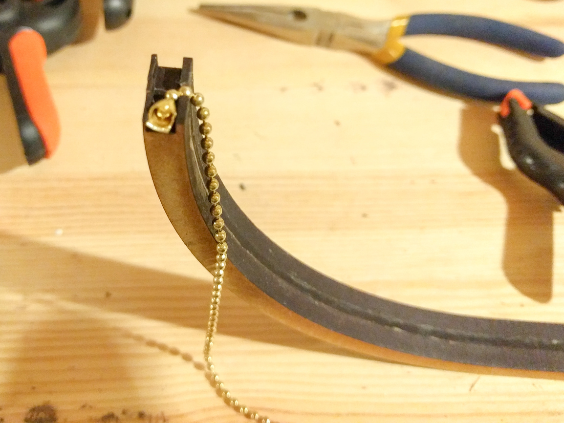
I should note, on my first lamp, instead of using this notch, I waited until much later in the build process, and I drilled a 1/2" hole straight up partway through the top of the hoop, and then I printed the little part in “repair.svg”, put some chain through the hole, and epoxied the chain and the “repair” into the hole. I actually like this solution much better, because you can do it much later after we’re done all the veneering and such. If you put the chain in now, then you’ll have this little bit of chain dangling around constantly getting into glue and other places where you don’t want it. So if you have a drill around, edit the SVG to close up that notch, and you can worry about the chain later. (Drill the hole before you veneer - you don’t want to accidentally drill through your veneer.)
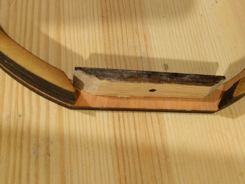
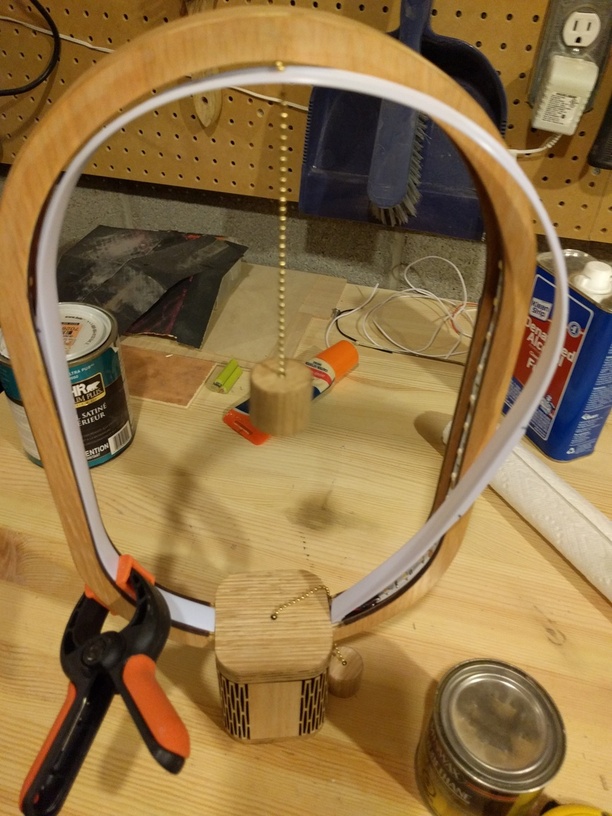
Once the ribs are assembled, grab the center piece of “TOP1” and some sandpaper and take the bottom two corners off (see photo below) - this gives you a little extra room to run wires.
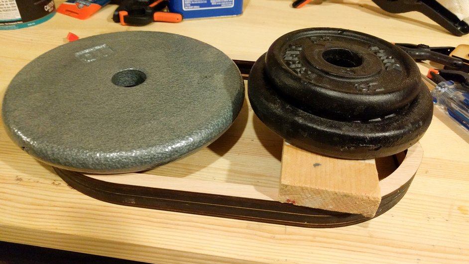
Put one of the hoops good-side-down on the table, smear glue on the backs of the ribs and the back edge of TOP1 and position them on the back of the hoop. Smear glue on top, put the second hoop on top, then stack some weights on top.
While that’s drying, this is a good time to make some corks - Glue some veneer to C1 and C6, let those dry, then glue C2 on top of C1 and insert two rare earth magnets. Glue C3 onto C2, C4 and C5 onto C3. Leave C6 alone for now, we’ll come back to that.
Your hoop should be dry now; you need to veneer the outside of it. Before you veneer it, if you’re as terrible at lining up all the ribs and hoops as I am, you should probably sand down the edges a bit to get rid of any irregularities. If you have an oscillating edge sander, it will save you some time here. But if you don’t, you can do this by hand.
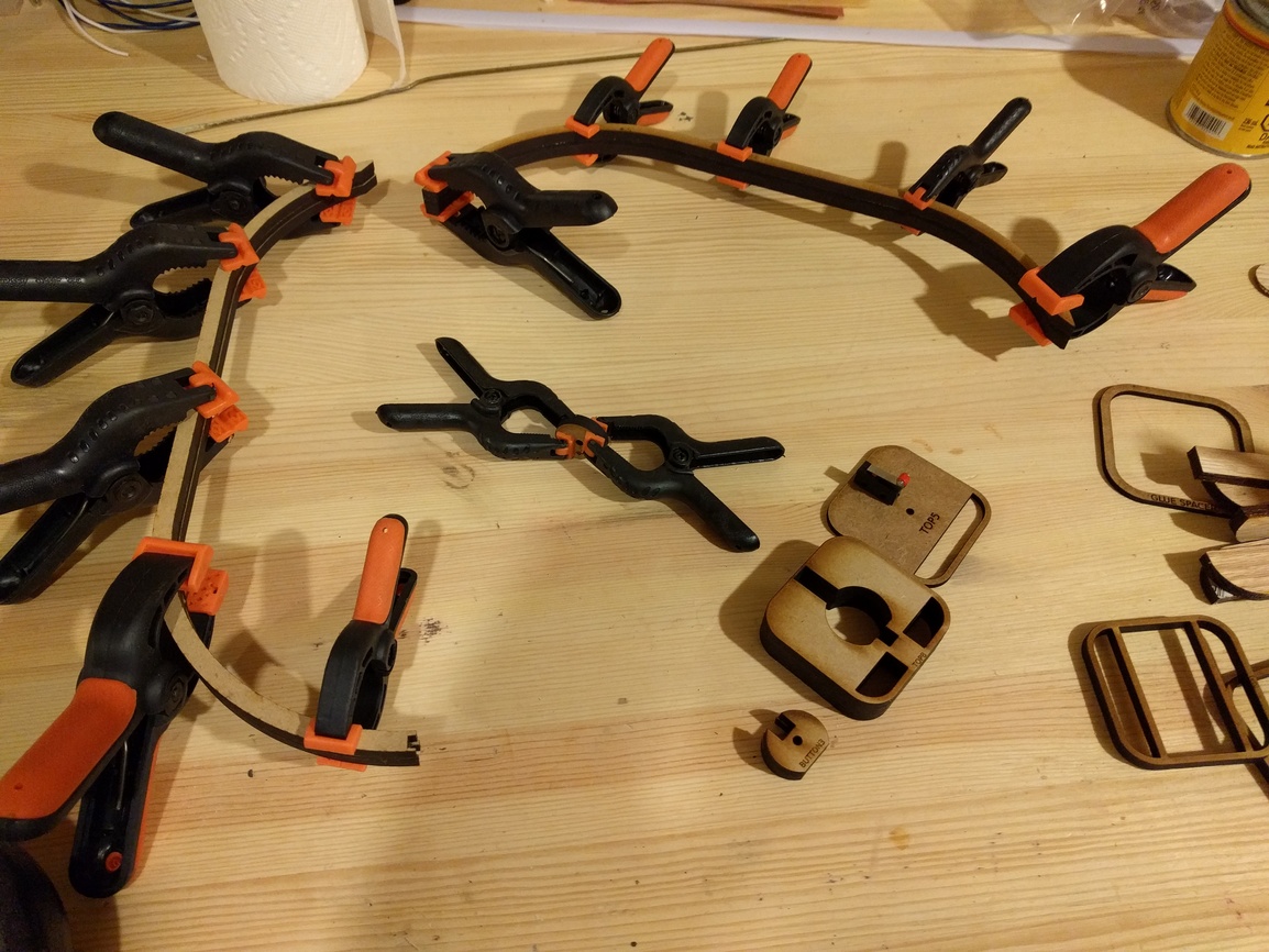
The veneer for the hoop is too long to cut on the GlowForge, so you need to do it the old fashioned way - cut a piece of veneer that’s a little too wide, smear glue on the outside of the hoop, and use a lot of clamps. Then, use an edge trimmer or carefully use sandpaper to trim it down. Alternatively, you could cut some strips of veneer 25mm wide, and as long as you can - maybe with a “puzzle piece” join at the ends to match the joint at the back of the lamp.
Once the glue for the veneer dries, I like to use a little sandpaper to slightly round the edges - nice sharp edges look nice on any woodworking project, but nice sharp edges are also very easy to damage, so they’ll be full of little nicks and dents after a little use. Slightly rounding off the corners makes them much sturdier.
Next step is to glue the two TOP1 and TOP2 pieces together, sand off any burn marks from the laser, then glue them onto either side of the base of the lamp. Glue TOP3 to TOP4, and glue TOP6, TOP7, and TOP8 together. You can also glue the veneer onto the top of TOP1.
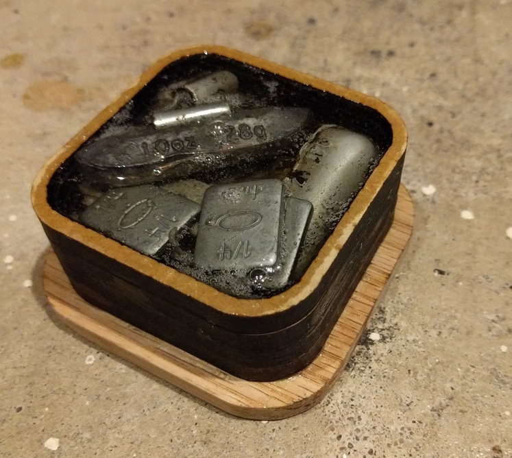
Also, glue the BOTTOM pieces together. When gluing BOTTOM2 to BOTTOM1 (the 1/4" oak piece) you can use the part labeled “GLUE SPACER” to help center BOTTOM2 on BOTTOM1. Fill the bottom with lead shot, or your weight of choice (I used some discarded wheel weights, scavenged from my local tire shot), and then either print a top to glue on to seal it up, or fill the whole BOTTOM with epoxy (or both!) If you add a piece to the top, be careful that it doesn’t interfere with the AC/DC port in the side wall.
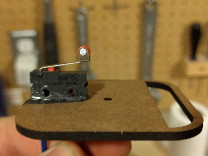
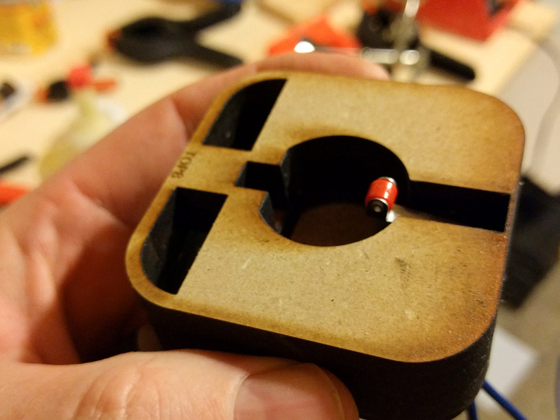
While we’re waiting for all that to dry, it’s time to get out the soldering iron. Solder two 10" long wires to the C and NO pins on your microswitch (C is for “common”, and NO is for “normally open” - the switch is open until you push it down, and then it’s closed). I used blue wires for this. Thread these wires through the appropriate holes in TOP5, and epoxy the microswitch to TOP5. When the epoxy is dry, you can glue TOP3 through TOP8 together into a single piece - make sure the microswitch is facing down into the circular hole in the bottom (the TOP8 side).
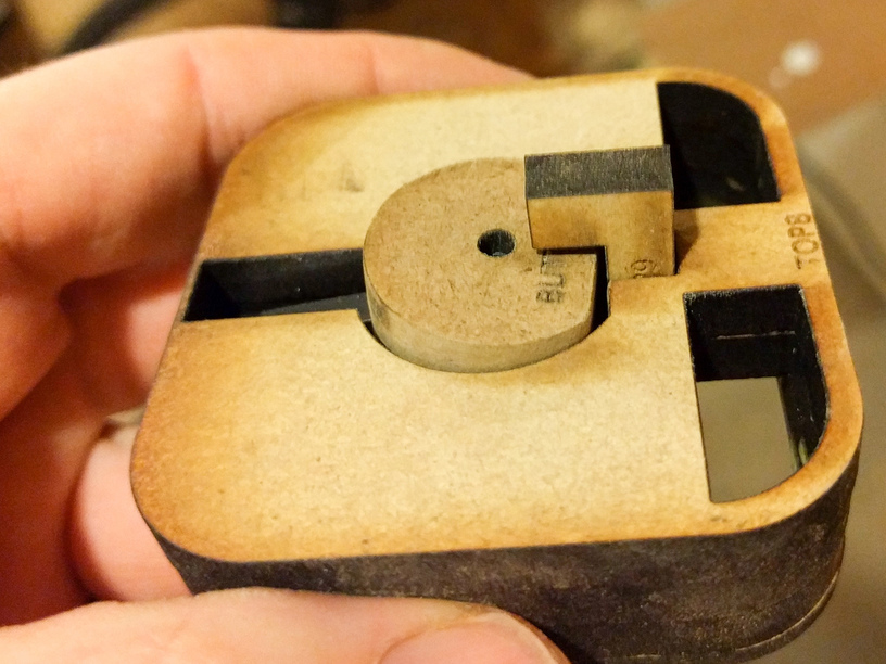
Glue together BUTTON1 through BUTTON4. This slides into the bottom of TOP8. I used some sandpaper to heavily round all the corners and edges on BUTTON1 to make sure it wouldn’t get jammed inside of the TOP pieces. TOP9 will eventually get put into the bottom of TOP8 to stop the button from falling out, but we’ll get to that a bit later.
Cut two approximately 14.5" lengths of LED strip lights. Solder leads to these, peel off the sticky back, and put them into the hoop. I put a little dab of epoxy on the wires to hold them firmly to the hoop, so if I tug on the wires later I won’t accidentally pull them off their solder pads. If you need help soldering the wires on, here’s a handy YouTube video. I used red for positive, and black for negative.
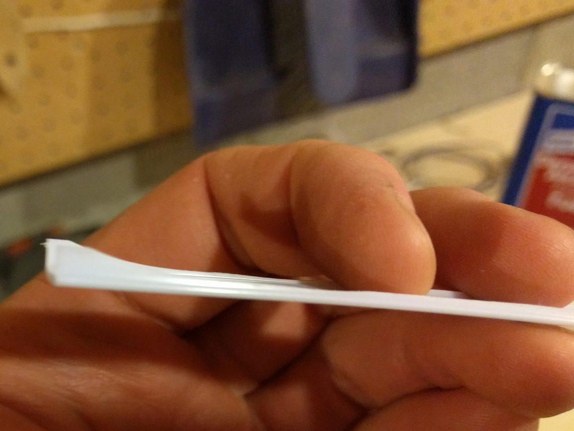
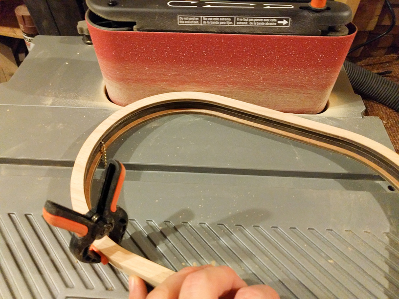
Grab your diffuser. When @m_raynsford did this, he cut his diffuser out of some polypropylene, and this sat in a little recess in the hoop. This is a much better design than what I’m about to get you to do.  But I didn’t know where to find polypropylene, and I was already at Lee Valley, so I just bought a 3’ long LED diffuser that’s meant to go into a channel. You cut the diffuser to 29 5/16" long, and drill a hole in the center big enough for your chain. If you’re using the diffuser I used, you’ll find the “ribs” on the back that sit in the channel don’t like to go around corners very well, so I used a belt sander to grind away almost all of the ribs from the ends to about 4.75" in, and then from 9" from the end to the center. Leave the full height of the rib at the very ends though; these will stop the diffuser from jumping out of the slot and sliding across the surface of TOP1 (see photo below).
If you haven’t installed the top chain yet, now is the time to do it. Cut it to length so the top cork is dangling about halfway down. Slide the center of the diffuser over the chain. Getting the diffuser in is a bit of a challenge. I put one end in, bend it around the corner, clamp the diffuser in place to stop it jumping out, then I did the same on the other side, and then finally I bent the center of the diffuser inward and snapped it into place. This is… exciting.
After you get the diffuser in, it’s time to deal with C6 and the rest of our corks; run the top chain through C6 (make sure you have the veneer on the top side), put an anchor on the end of the chain, and glue C6 to C5. You can fine tune the length of the chain a bit here (well, you can make it shorter).
We do the same to the other cork with a length of chain. Run this chain down through TOP1 and TOP2 - it’s a good idea to put an anchor between TOP2 and TOP5 to stop the chain from disappearing down into the body of the lamp (I forgot to do this on my second lamp).
Once you have both corks fully assembled, it’s time to veneer them. It’s much easier to do this if the grain of the veneer runs up and down along the axis of the cork. Also, getting the veneer wet will help. If you weren’t super careful about lining up the corks, or if the veneer doesn’t quite stretch all the way around the cork for some reason, you can lightly sand the sides of the cork to make it slightly smaller. If you have the opposite problem, and the veneer is too long, hold the veneer by the top and bottom edges, at 90 degrees to a piece of sandpaper, and lightly sand the end.
Run the mess of wires from the LEDs and the switch down through the stack of TOP pieces, and run the chain down through the middle. Be careful to route the wires away from the chain. You can cut a couple of extra C4 rings and stack them around the chain hole to be extra sure the wires won’t be rubbing against the chain. Slide the “GLUE SPACER” piece around the TOP stack, and use it to help you center TOP3 against the bottom of TOP2. After you clamp everything together, slide GLUE SPACER a little away from TOP2 to make sure it doesn’t accidentally get glued there. (You might want to hold off on gluing TOP2 and TOP3 together until you fine-tune the length of the bottom chain.)
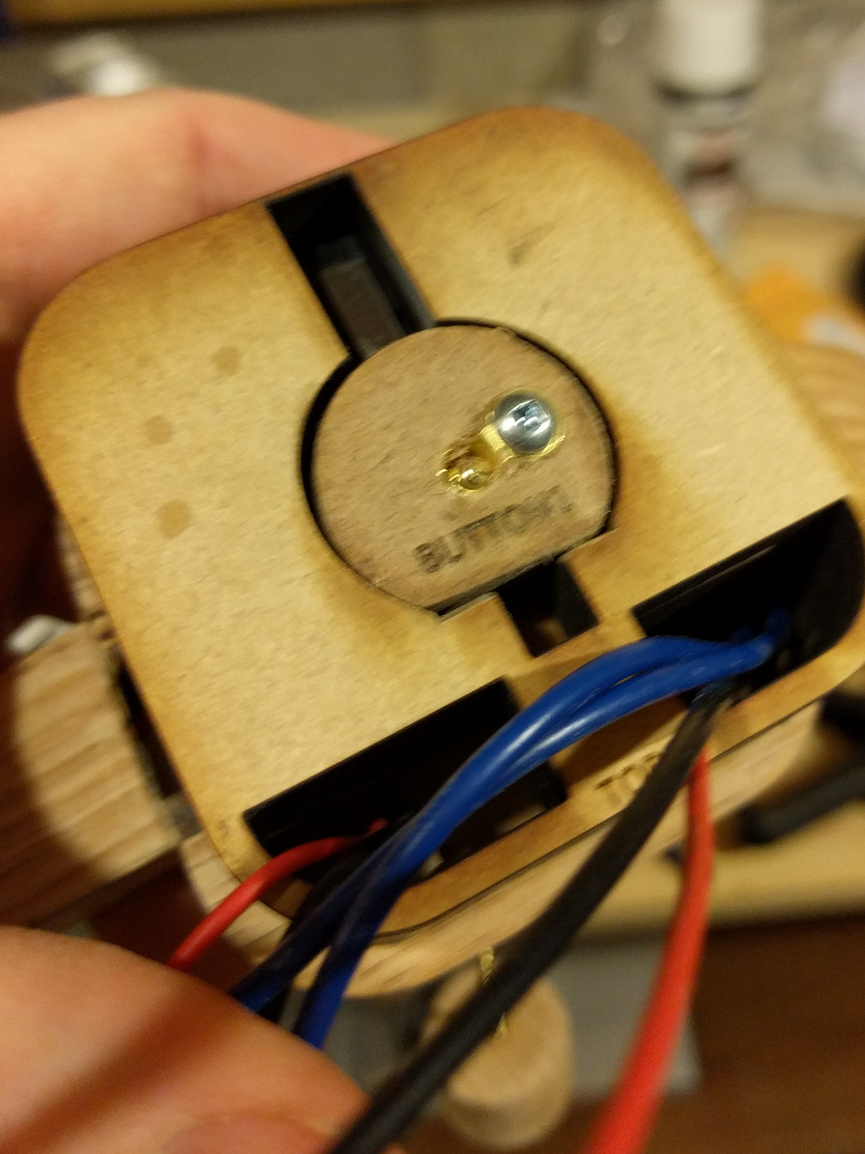
Slide your chain through the BUTTON, and put the BUTTON up into the TOP. Attach an anchor the chain under the button. This is your chance to fine tune the “gap” between the two corks. You want as big a gap as possible, but you want the gap small enough that the switch is reliably triggered. You can easily move the anchor around to try different heights. I used a drill to make the hole in the bottom of BUTTON4 a little bigger, so I could slide an anchor right into that hole. I bent the ring of the anchor at a 90 degree angle and put a screw through it, to stop the chain falling down into the main part of the lamp.
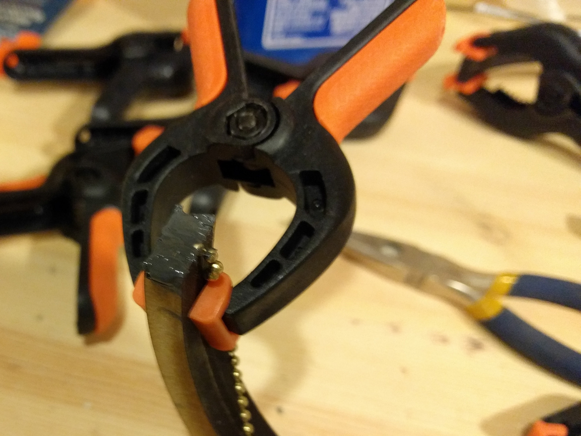
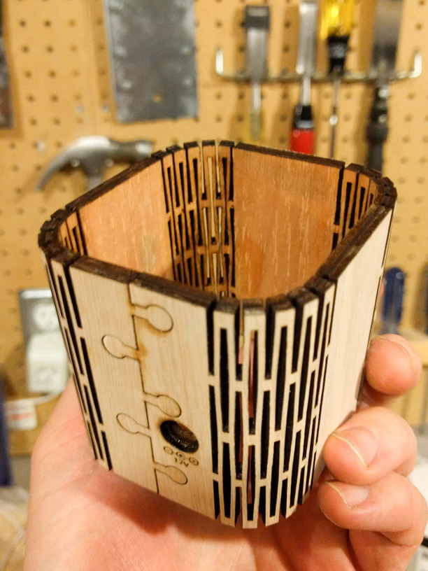
Grab the living-hinge part of the base. I found it was a little hard to get the hinge to wrap around the tight bends of the base without breaking. I tried a few different variations on the hinge. What I found helped quite a bit was to get out my clothes iron, and squirt a few blasts of steam at either side of the hinge before I tried to bend it. The “puzzle piece” join at the ends of the hinge is set up with a 0.01" kerf compensation for the GlowForge. Use a clamp to “press” the pieces together.
Grab the AC/DC socket and test-fit it in the hole. On my AC/DC socket, the threads on the outside for the nut that holds it in place were about 5mm thick, so I had to engrave a recess into the outside of the plywood so there was some thread for the nut to engage on. Make sure you can get the nut on - if you can’t, then use a Dremel or similar to make that recess a little deeper.
Cut the positive wires from the LED (red) down to a reasonable length, and one of the switch wires. Solder the two positive wires from the LED strips together, and then to a wire from the switch. I used some heat-shrink tubing to protect the solder joint from getting bumped into by the chain or other metal bits. Solder the two black wires together. Take the negative LED wires (black) and the remaining switch wire, and slide a hex nut from the AC/DC socket over them. Push the wires through the top part of the wall (the part furthest from the AC/DC socket hole) and then through the AC/DC socket hole. Cut to an appropriate length. Solder the wires to the AC/DC socket. The black should go to the longer pin, which should be the outside of the AC/DC socket, and the switch should go to the smaller one, which should be the center pin. If you get it backwards, the lamp won’t light up. Again, I used some heat-shrink tubing to wrap these joints - if somehow there’s some chain down in this part of the lamp, you don’t want it to short out these leads. This is a good time to plug in the lamp and make sure it lights up - if it doesn’t, this is your last chance to fix things. When you’re happy, use the hex nut to secure the AC/DC socket in place.
Put glue on the outside of the TOP and the BOTTOM. Slide the wall up over the TOP, and then slide the BOTTOM into the bottom. It’s a good idea to clamp the outside of the walls here while you wait for this to dry.
That’s it! Enjoy your lamp!


 ). They also have some pre cut BB ply and way cheaper then KJB. KJB does have the off cuts by the pound box, which is fun to pop in on.