A few years ago I took it upon myself to start learning a 3d design program because I feel that is the way Jewelry design is going. I’ve only learned 1 aspect of this MASSIVE yet free program… and that is 3d modeling. I’ve not even really learned rendering…
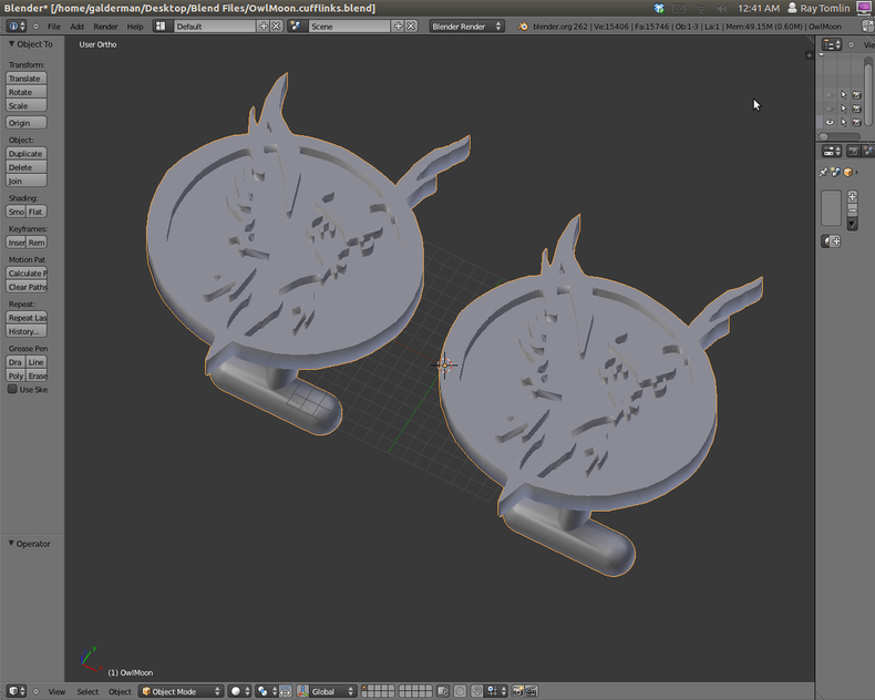
So, all that being said I wonder how I can turn some of my 3d models into layered designs to be cut out by a glowforge. Ohh and some examples of my designs.
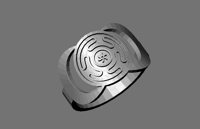
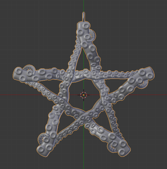
This first one is using a Greek design called The Strophalos, and the moons are inward pointing to represent the dark of the moon.
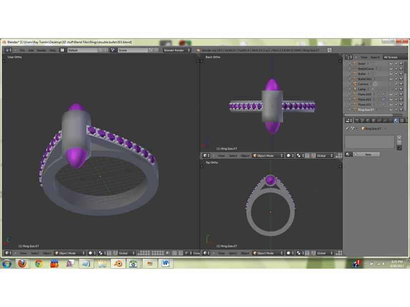
The idea here was to bead set Amethyst and also have 2 Amethyst bullets set into the side of the tube. I’ve not made this yet… since the metal is too costly.
I’ve installed Blender a couple times, but I think I gave up on it quickly. It’s one of those programs that is very powerful but also very complicated, right?
Is it capable of outputting 2D vector files? The 2D stuff could be made with a laser if you could get the outlines out of Blender in a file the Glowforge could read.
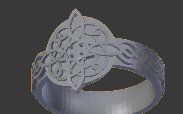
I’ve seen some rings being made in various videos, but never done it myself. Seems like a couple of those designs (The Strophalos, the top part of the owls) could possibly be cut out as two separate pieces of thin, flat wax which would then be layered on top of each other and bent into a circle. If it works for those, the main features of that awesome looking wedding ring could be made in a similar way, but the overlapping strands would be pretty darn hard to replicate.
Those look like perfect candidates to be printed with something like a Form1 (or Form2) 3D printer. If you have one you don’t mind sharing, I’d try it out with my Form1+ if you want. I don’t have any of the lost wax style resin, but I could print it in clear or something. An STL file would be all I’d need.
Thanks for asking this. I have wanted to slice stuff, but never gotten around to figuring it out until just now. Not exactly what you were asking, but I’ll put it here since it was what got me going.
This worked for me. It uses FreeCAD and some Python script to slice stuff. To get it to work, I had to remove the end of the script where it mentions the name of the model used in his example and the period, re-type the period, and an autofill list of stuff from my model showed up for me to put the proper thing in. I’m not a programmer, so autofill saved me here. Didn’t have a clue. The script is below with notes on what I mean. Definitely some work to do after that and possibly some figuring out of modifications to the script if necessary, but this is much further than I’ve gotten before. If anyone that IS a programmer could point out useful changes, that’d be greeeat (Office Space reference.)
from FreeCAD import Base
import Draft, Part
App=FreeCAD

def slicePart(ob):
	shape=ob.Shape
	g2=App.ActiveDocument.addObject("App::DocumentObjectGroup",str(ob.Label) + "_Slices")
	b=shape.BoundBox
	print shape
	lx=b.XMax-b.XMin+5
	ly=b.YMax-b.YMin+5
	h=b.ZMin
	l=0
	bb=0
	dh=1
	while h < b.ZMax:
		print h
		try:
			wires=list()
			for i in shape.slice(Base.Vector(0,0,1),h):
				wires.append(i)
			comp=Part.Compound(wires)
			slice=FreeCAD.ActiveDocument.addObject("Part::Feature","MySlice")
			slice.Shape=comp
			slice.purgeTouched()
#			del comp,wires
			t=FreeCAD.ActiveDocument.addObject("Part::Extrusion","Extrude")
			t.Base = slice
			t.Dir = (0,0,dh)
			t.Solid = True
			t.Placement.Base=FreeCAD.Vector(l,bb,-h)
			l += lx
			if l >400:
				l=0
				bb +=ly
			g2.addObject(t)
		except:
			print "FEHLER"
		h += dh
	# del shape
	App.activeDocument().recompute()
# main


slicePart(App.ActiveDocument.Pocket)
That last line “slicePart(App.ActiveDocument.Pocket)” I deleted back to the first period, maybe a letter or two more, then put back the “nt.” and a list of valid choices came up to autofill the correct reference.
I’m going to whine. I’m a Linux user and that is what we do. We whine about how “they” don’t release stuff for Linux. (emoji goes here to express humorous intent)
Also, I haven’t gotten 123d Make running. I’ll give it a go now. (smiley emoji here)
that one is easy too! get a copy of virtualbox (or dual boot) a windows partition and run whatever software you need to. Thats what I did on my mac until I put together a new windows box.
I’ve have been playing around with designing things in Cinema 4D which should be similar to design in Blender.
So far I mainly use it to quickly model out my ideas since i’m much quicker in Cinema then in Fusion, and then recreating them in Fusion.
But i think it I may have got a workflow for getting my designs directly out of Cinema.
Basically if i create my cut shapes off to the side and then make an instance of the shape and extrude that to the material thickness. This lets my move the instances around to build my 3d object while still editing the 2d shapes in the top down view. Then i just export the shapes to illustrator for for final layout.
It works fairly well, but is not as exact as working in Fusion. So for that reason I will probably still end up creating my final files in something like Fusion.
One huge advantage of Fusion is that fusion (or other full CAD/CAM) is the whole CAM part. CAD is pretty generic at this point, but to support a usable laser output you want all the assistance that CAM workflows give you (tabs, dogbones, waste material optimization, etc). 3D modeling packages like Cinema 4D are designed to produce 3D animations which often don’t work quite as cleanly as CAD geometry in the real world. In screen rendered objects cheating is considered a good thing, while in the real world, unfortunately geometry needs to be “real”.
The best example is when I take a 3D model I make from a CT scan, on screen the bones look gorgeous but the geometry is totally invalid in “real” space. The triangles are inside-out or overlapping vertices, etc. I reconstructed a tibia/fibula recently and despite being a simple model, had 12000 non-manifold polygons, inverted normals, etc since screen and CAD/CAM geometry really have different standards of accuracy.
Most of those designs look like they would 3D print (with higher end printers – would not work well with cheap FDM printers).
Try sending the STL file to shapeways.com – order the design done in “White Strong and Flexible” plastic (aka nylon, pretty cheap) to see how the shape works. Then if you like it, you can order it again in steel, brass, bronze, silver, platinum (yeah, right!), and more.
For stones, it takes a bit more work to design a setting that can be clamped down after printing. For that, order the metal unpolished (so prongs don’t get lost), set the stones, then polish yourself (assuming you have a buff wheel or foredom tool).
Hint: I’ve done this with my own earring and cufflink designs, and more than a few optical instrument parts.
Ohh I already work with them. Of the pictures I posted I’ve printed all but 2 at Shapeways. The one with the purple stones I’ve not refined enough to print, and my wedding ring I went with another company for better results and a better material. As a jewelry designer, I know the power of 3d printing and the services that Shapeways can offer.
I’d treat it as a bezel set cab.
Amethyst being a quartz is hard enough to withstand significant pressure. (which makes it a good choice for a ring) I usually put a bed of sawdust under the stone on any ring designs just as a cushion because of the abuse rings are subjected to.