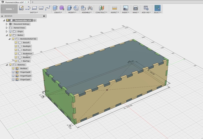
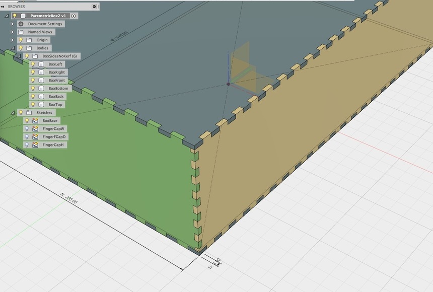
Here is another parametic box design in Fusion. The outside dimensions, material thickness and number of finger joints can be adjusted in 3 axies from the Change Parameters tab in the Modify Menu. I hadn’t seen one here that you could adjust the tab count in this way so, I though I would post mine. The number in the Tabs Slot box will control the tab count, an even number will give you slots on the outside corners and an odd number will give you tabs so you can control how your corners look. You can ignore the parameters for kerf thickness and beam width, its something I use after my design is locked so its not live here.
ParemetricBox-Brotron2.f3d.zip (883.1 KB)
Fixed an order of opperations erorr where changeing the depth tab number would break the box, hopefully all working now. One little caveat is that if you enter in too many finger joints the overlap at the corners will create extra bodies that break the system… so not a perfect method, I have to find a way to put a limit or offset on the corners.
So this box is proving to be fairly stable with large numbers of fingers, what you have to watch out for is entering a value that would make the fingers smaller than the material thickness. For instance, if you had the box above that has a material thickness of 3mm and you entered in a material thickness of 22 mm then it would all go to hell, but if you took your finger joint count very low then made it 22mm, no problem. The same would happen if you made the dimensions of the box above very small without reducing the joint count or the thickness first. If I could write (Else, If) statements into the rules it would be easy to put in limits but they don’t have that yet.
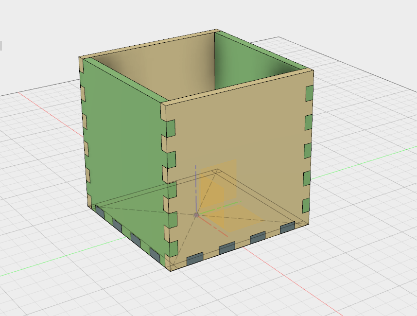
I adjusted the parameters for thickness, length, width, height, number of finger joints (not actual names), until I got something I could use as a 80x80x100mm pen cup.
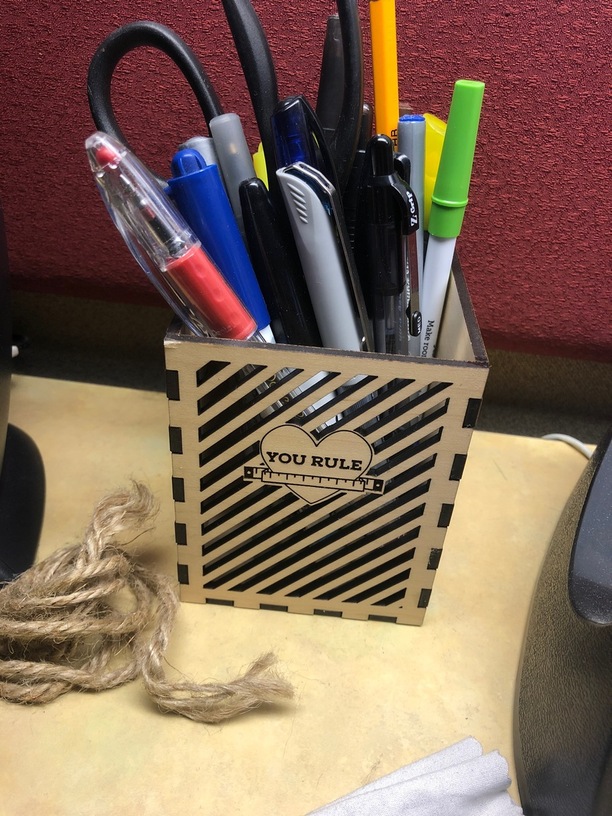
Everything turned out great (especially once I added design elements (like the “You Rule” design from @reliablepants) but the finger joints seemed a little loose. They definitely needed clamping in order to be glued.
Do I need to adjust kerf settings for different materials?
Glad it worked out, looks great!
This design does not adjust for kerf, so you have to adjust it manually for your material. You can add an offset in fusion before you export, or add it in your vector program. I have a parametric way to adjust kerf after the box is done but didn’t include it since it breaks the adjustability of the box. Still working on getting kerf and tab count to play nice together.
Sorry to ask so many questions. Was going to do another run at this and try adjusting kerf. In your design, you have BeamWidth = 0.07mm and Kerf = BeamWidth/2.
Maybe this is really dumb, but I though the Kerf was the BeamWidth, and folks were adjusting in/out by half a Kerf… no?
It was just easier in the code to say offset “Kerf” so I made two categories, one that had the division imbedded and the other called beam width with is the actual kerf. It’s not linked to anything so you could rename them anyway you want if you are designing an offset.
You are correct, for all intents and purposes the kerf and the beam width are basically just two ways to describe the same thing. You are also right about kerf correction, when you adjust for kerf you only offset by half the kerf width. This is done because the machine centers the spot of the laser beam on the line.
As an analogy, imagine the laser spot is actually a car driving down the road. Now imagine the car is controlled by a computer that needs a purple line painted in the road and that the computer is programmed to keep the car centered over the purple line. When painting the purple lines for the car to follow, you’d want to make sure they are always at least 1/2 of the width of the car from the center line of the road. The laser basically works the same way and kerf correction also works the same way.
Second, you’ve stated that you adjust kerf using the parameters after you get the box setup. Can you explain how you do that? And/or how to do it during export to make sure it get’s done correctly? New user here and my next project is a case for my daughter’s markers, so this is a great starting off point. Thanks again!
One way to do this is to save the face you want to cut using the DXF for laser plugin. This asks you for the kerf size in mm and offsets the design automatically based on knowing what is inside and outside.
I’ve been using it more lately because keeping the kerf out of the design itself seems cleaner. Only problemb for me is that it doesn’t work for cases where I’d like some cut lines that are not closed loops (like for living hinges / kerf bending).
I was experiment with a second set of bodies that was generated from the parametric set that had all their own sketch faces linked with an offset. It worked fine for the box I had, but didn’t remain editable for finger joint count so I scrapped it.
Mostly I take the final dxf output into illustrator and do the offset there. That way my model is clean and I can change the offset of all the outlines at once. Then I save out the file with different offsets for different materials .
In fusion I select the face, make a sketch and use the offset tool (hotkey is “o”) and enter in Kerf for the offset. In my parameter rules Kerf is half the beam width, so it’s technically HalfKerf, but that is longer to type.
Have to check this out, it sounds much faster, thanks for the tip!
This is so cool, thank you for sharing!
Fusion 360 is one of those programs I need to learn how to use! I have experience 3D modeling about 10 years ago but kinda lost touch with it. Any tips on quick ways to get started with this file?
I finally got a chance to play with this file. Thank you so much! Now for one, I can see how it’s done. And for two, I can make a few quick boxes to play around with some designs.