I’m not going down this rabbit hole with you. The only thing that I’m doing is putting out there what the patent claims state. If you have an argument with what can be patented and what can’t be, please feel free to take it up with the USPTO.
5 Likes
patents are not my strong suit, but it may also only end up applying within the realm of laser cutters. regardless, here is the application:
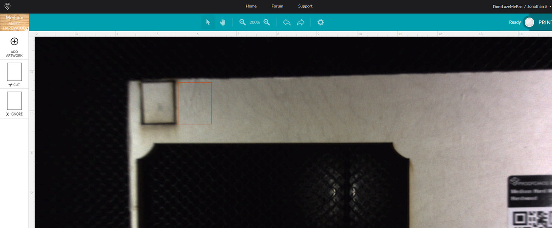
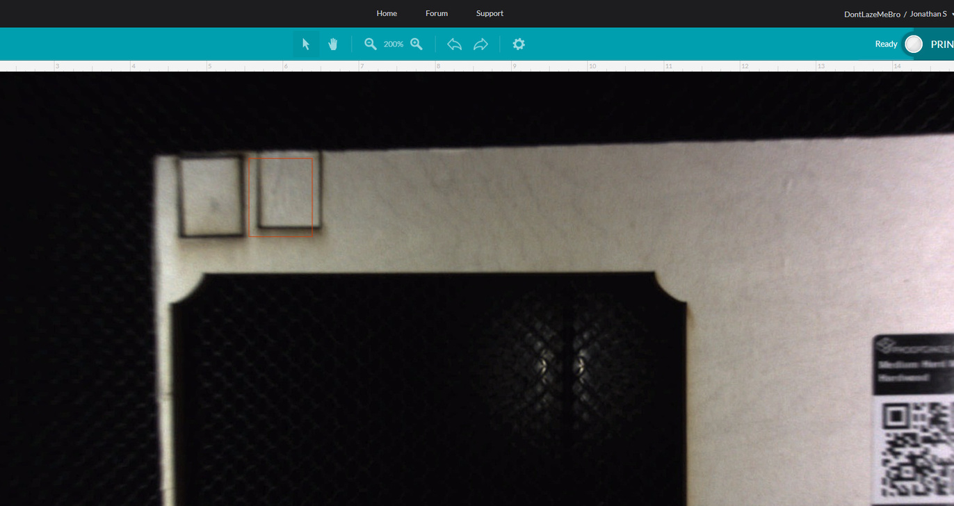
I mispoke, earlier. Mine looked like this with the cut image always to the left of the superimposed design image, even on the right side. Normally there is a little shift to the right on the right margins and a little shift to the left on the left margins, but nothing so drastic.
For a while yesterday, my design placements looked like this after a print. I didn’t save any screenshots of it. That reminds me that I should do a screen shot right before pressing the hardware print button but without the dialog in the way and after before opening the lid. That would be helpful for diagnosis if something is wrong. I used to do this for the first month or so, but then didn’t bother since I didn’t have too many issues that I couldn’t figure out right away.
4 Likes
Most patents are nonsense. People have been using cameras to preview laser beds long before Glowforge filed it.
1 Like
Well, there’s a little comfort in knowing I’m not the only one. But the thing that bugs me most is my first unit didn’t seem to suffer the problem. Of course, it’s also entirely possible I never went out to the extremes at times where that would matter. I dunno. Bumming me out a little though. I hope it all gets fixed soon.
1 Like
My opinion is never trust optical. Measure your piece and mock it up in illustrator. Put everything exactly where you want it there, and run a test engrave on cardboard/paper to see if the placement looks good IRL. If it does, run it on the final material.
Optical is nice for cutting stuff out of scrap, but its not reliable for extreme accuracy - Especially when the camera is attached to something that moves, and is adjustable.
3 Likes
Weird thing was how it went away. Here is a test screen overlay on cardboard. The targets are over the cutouts in the cardboard. Screenshot right after printing. Still pretty close. Bigger shift in the top right, but the cardboard isn’t dead flat so there is some error there.
3 Likes
This is disappointing.
Interesting we’ve different results. How can they possibly fix it if it’s inconsistent?
As I was saying earlier in the day… MATH! Or in this case…
Extracting distorted grid points for compensation of lens radial nonlinearities.
https://www.eurasip.org/Proceedings/Eusipco/Eusipco2007/Papers/A1L-F04.pdf
7 Likes
Use the head camera.
3 Likes
@Tom_A ,
I am experiencing the exact SAME issue and I notified support about it yesterday. I sent the the below before and after shots to support, and the notified me its something they are working on.
The worrisome thing is, before last week this machine was pretty dead on alignment. So I hope its something they can fix.
I have been doing what @takitus has suggested and laying everything out in illustrator until the alignment gets a little better.
The annoying thing is I find myself leaving a 1/4" gap around my work area to account for alignment offset, which is a waste of material.
2 Likes
I’ve seen it get better in the last six months. I’ve seen it get more offset at times while there was an software change, but then it always comes back with an improvement. After the big addition of more usable area in May, that made the center part of alignment get much better. Whatever they are working on for the GFUI code, there have been improvements. But as was recently stated by support, the best way to align is the center of the machine; that doesn’t mean you shouldn’t be getting good results at the perimeter, just not sub millimeter accuracy at this point.
5 Likes
If it worked great before, that’s really super encouraging to me, since it was probably a software change that caused it. There be geometry and optics and math here…
4 Likes
When I start my other project that will have VERY tight tolerances for the top and bottom of the material, I’m planning on running a light score around the outlines just to make sure everything will appear where it should, before I laser, score, cut the final piece. It’s the only way I know to REALLY see if something is aligned properly.
3 Likes
I have never tested the accuracy of my camera, mostly because I have had great success with cutting small shapes out of scraps and never felt the need. I am also expecting that once the head camera is enabled we will have pretty extreme registration capabilities. This thread has peaked my interest in the exact tolerance of my bed camera however, so I decided to run some tests.
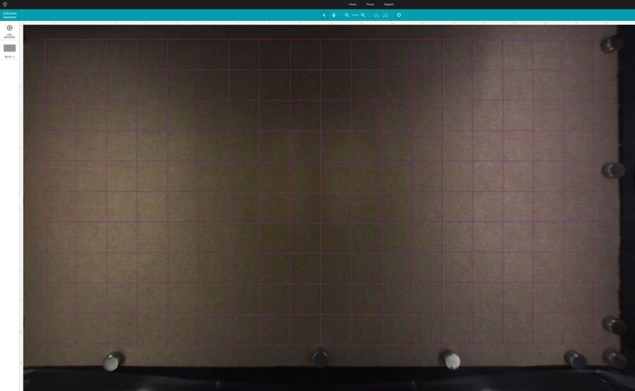
I created a 1" grid pattern and scored onto some scrap cardboard. The cardboard was not a very good test material however because it had both bowing/warping issues as well as I measured pretty inconsistent thicknesses ranging from .16" to .175. I used .17" as my initial value for the focus height. I placed magnets around the parameter in an effort to minimize warping issues, but there was still some areas hovering above the bed.

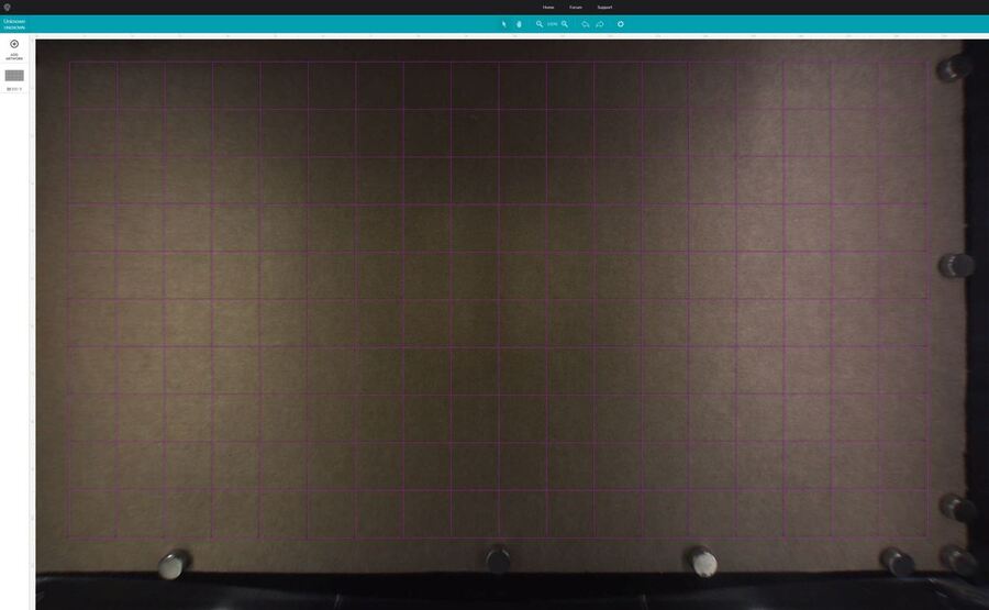
Bed image before scoring, focus set to .17"
Bed image after scoring (no shifting of the grid), focus still set to .17". I could see some minor shifting so I started playing around with focus settings. I found .15" got pretty close to an overlap of the scores and the vector grid.
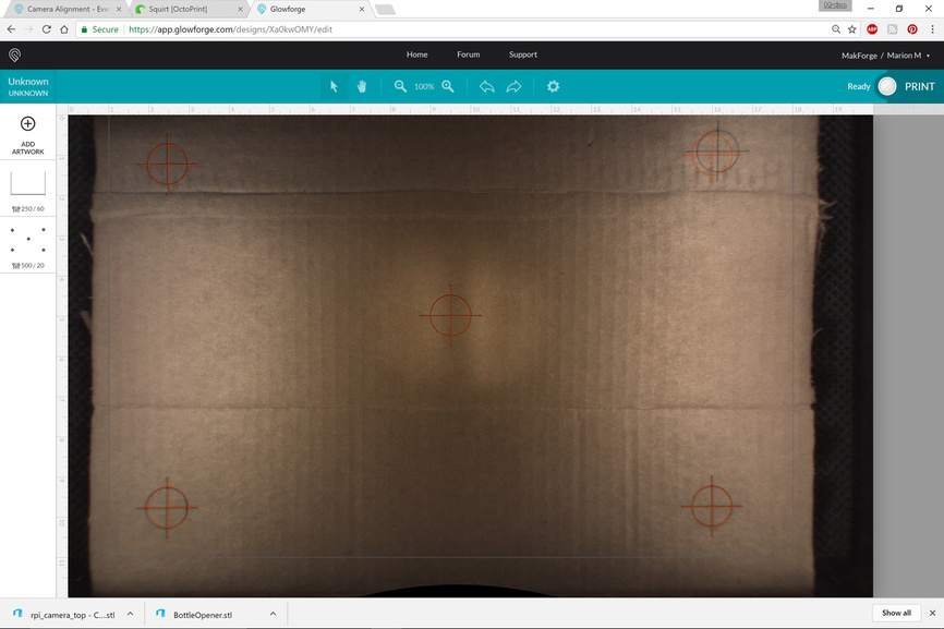
Bed image after adjusting focus to .15". I decided to bring in a target point to try to line up and then score over the grid lines now on the cardboard. I placed each one individually by eye at 200% zoom in the GFUI.
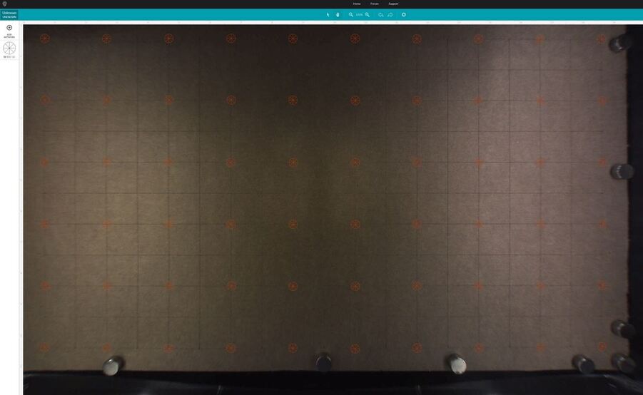
Bed image with focus at .15" and all the target points placed by eye.
Bed image after scoring targets. Focus still set to .15".

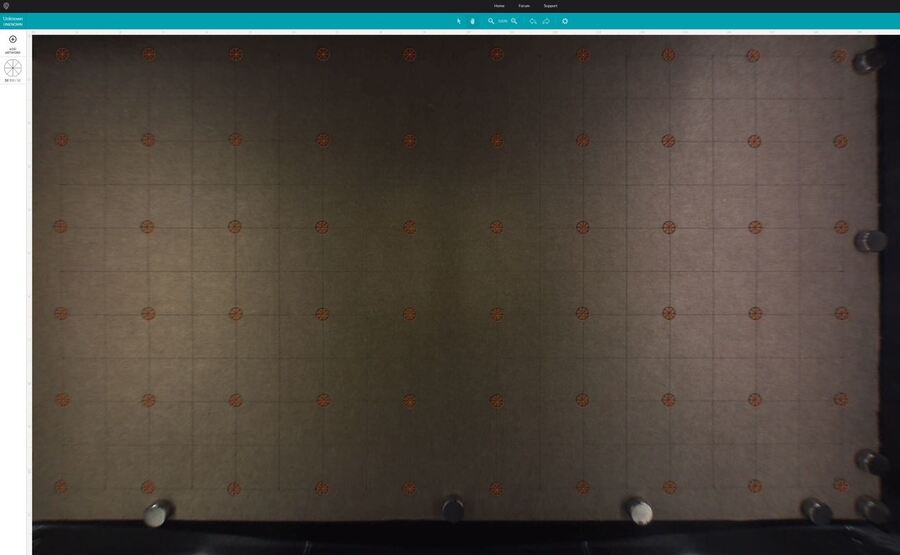
Bed image with new targets (no circles) focus now set back to .17".
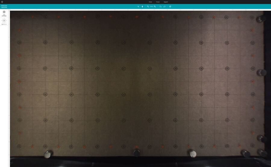
Bed image with new targets scored. There was more of a visible shift for sure.
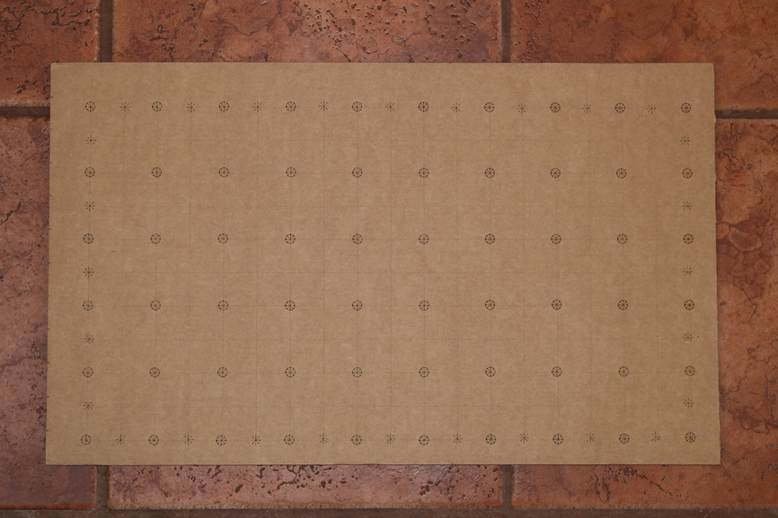
Photo of results.
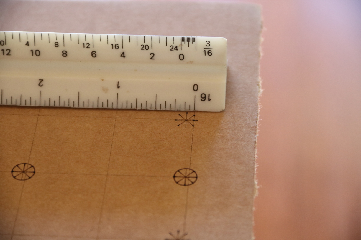
Worst case, focus set at .17". Offset less than 1/8".
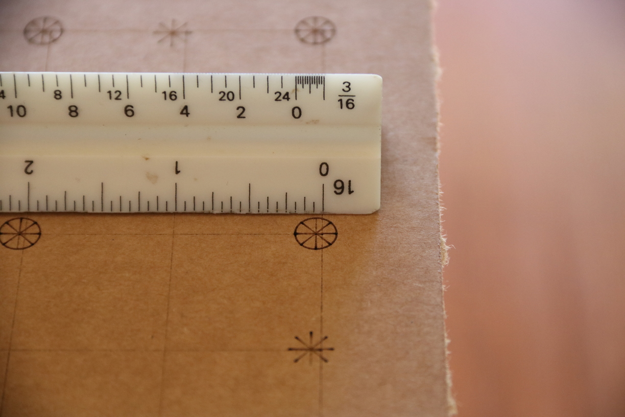
Focus set to .15". Offset less than 1/16".
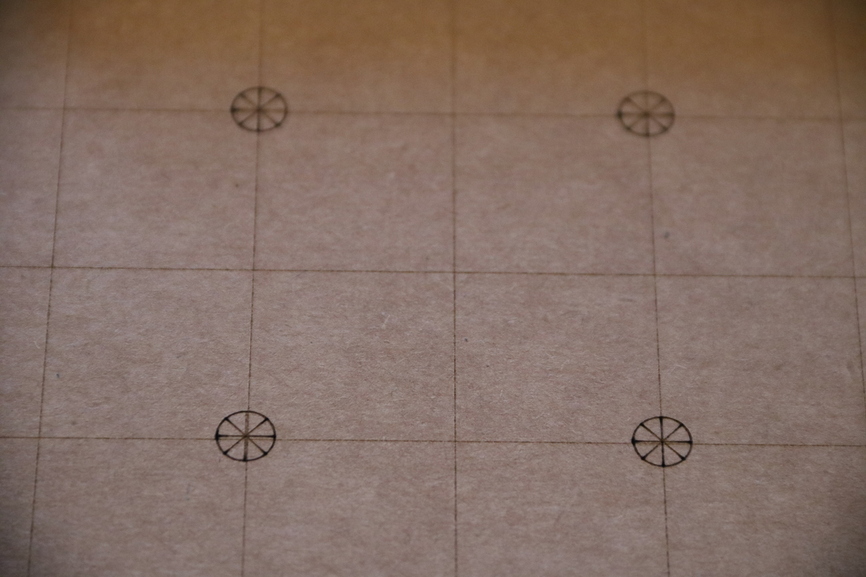
Finally a shot of the four most central targets.
This test would have been more meaningful with a more consistent material like Proofgrade. That being said, should anyone wish to try to replicate on their end I will provide my SVG files.
TestGridSVGs.zip (1.9 KB)
22 Likes
Very interesting. So a 0.02" difference in height makes about 1/16" = 0.0625" difference at the edges. Probably about right as it could be three times further from the lens to the edge than it is straight down.
3 Likes
My magnets are .12" thick, yet they look like little towers in the extremes of the bed image.
3 Likes
Fantastic job testing that! 
2 Likes
I’m working on some invitations for friends of mine. The entire cardstock is 11" x 8 1/2" which will be cut down to 10" x 7". The inside right side is a 5" x 7" photo with information of their event, the left side is a cut design. There is a cut line for the previous dimensions. I can not line up the design and cut even with the photo. It’s impossible with the way the camera is now, have been lucky s few times though. I’ve even made a jig for the paper to ensure the cardstock is straight. Unfortunately, the image in the UI is not.
Reported to support.
This is a problem that obviously needs to take priority!!