As long as the force is constant only the one contact side is relevant ![]()
2 Likes
Exactly! If the teeth are to close, they will rub as enter/exit.
To ensure a perfect connection, I need to adjust the wheel and the pinion it interacts with. And after playing with some math, it looks like I can get the desired ratio by changing one of my 60 tooth wheels with a 64 tooth wheel, and its corresponding 16 tooth pinion with a 15 tooth pinion.
This will make a slightly larger wheel, but I think if I swap the minute wheel it should have enough clearance for the larger size. And if all that works, I will not need to adjust the frame.

3 Likes
I swapped out the gears for the newly designed set, but something else appears to be dragging on the gear-train.
I probably need to take it apart and give it a good cleaning, then lubricate axles (lightly). It could also be the frame shifting again, but this does not feel like it is the same issue. It feels less consistent.
So, after work today I started removing my gear assemblies one at a time while slowing turning the bottom gear to feel when the pressure built up.
I started with all the gears in the train. When I started turning, all was fine. Then it felt like I was pushing uphill and then it would get over the hill and speed up until it felt like I reached the hill again. It felt like something was rubbing, acrylic on acrylic. My first thought was that maybe my gears are too close together, causing them to rub, but I checking them all and they looked fine.
Next I pulled out the minute cross-axle (I have always been suspicious of it), but the resistance was still there. So returned the axle to its place.
Then I removed the escapement assembly. Started turning the bottom gear, and it was much smoother. (Huh?!?) So I started examining the frame and found this:
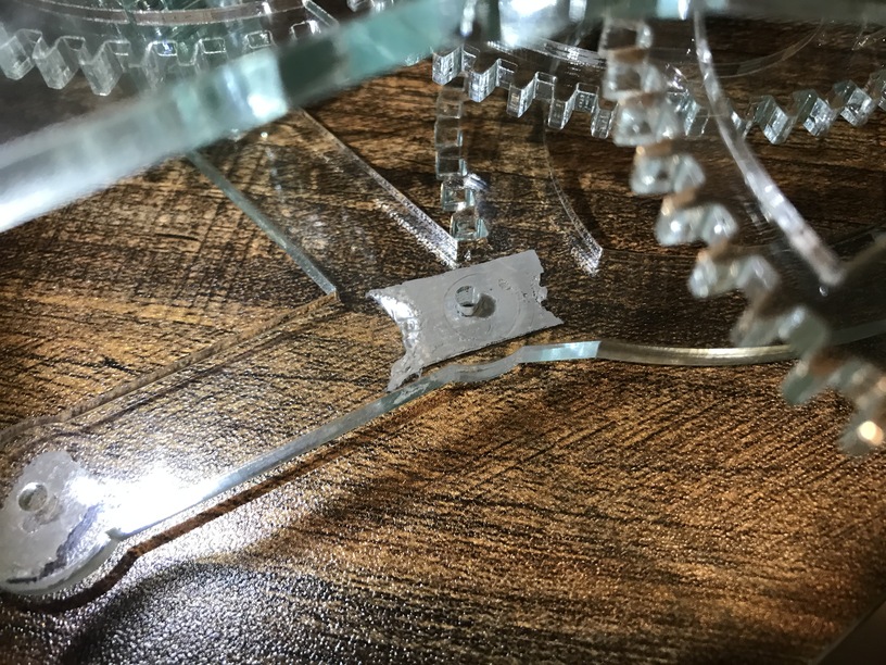
Not sure if you can see it in the photo, but there are small circular scratches in the acrylic frame around that axle hole (often referred to as “witness marks”). I believe I have found my friction point in the chain.
I am going to clean up this assembly and lubricate the brass-bar and acrylic-washers and see if my clock will run again.
The clock ran all night! It is still running fast though and if I adjust the pendulum slower again I am afraid it will stop…
I might reinstall the previous 64 tooth gear in place of the original 60 tooth one again now that I found the issue with the gear chain.
1 Like
Well, the clocked stopped again while we were on vacation.
Previously, I had found some thin clear acrylic at Home Depot. It is around half the width of the green-glass acrylic, so I cut some extra frame spacers to ensure there was plenty of room for the axles to spin. (That appears to be where my issues are with the frame currently.)
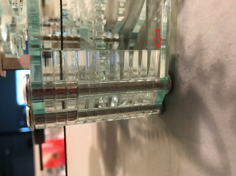
If you look really hard you can see different layer.
While checking out the movement of the axles in the new spacing I also noticed the drum axle twisting.
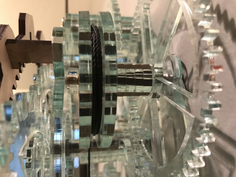
I don’t think this is a problem. But this is also why I have four pegs holding the axle layers together.
The clock ran all night, AND is reading the correct time! (I don’t remember how close it was to correct when I went to bed, so it might just be a coincidence…)
I think I will go ahead start packaging up the SVGs after work today, because I think this is finally working again.
3 Likes
The clock is running really well (if a tad fast).
Here are the designs!
(Primary material - part 1)

(Primary material - part 2)

(Thinner secondary material)

(Medium Draftboard/Ply - 1/8")

(And all four zipped up)
Glowforge Clock v1.6.1.zip (335.5 KB)
This certainly is not for the “faint of heart” but extremely rewarding if you get it working.
I cannot promise I didn’t forget anything, but I do promise to update this if I do discover something missing!
15 Likes
I will not be attempting this, but I appreciate all of the work you have done, the write ups you have shared and these files. Quite a project!
2 Likes
Thank you @bill.m.davis for your generosity, but as much as I love clockwork and  , I’m afraid this proyect is beyond my current capability. I will bookmark it for the future.
However your persistance and tenacity in seeing this project through has been inspiring!
3 Likes
I tried swapping one of the 60 tooth wheels with the 64 tooth wheel (same diameter), but it did not go well. So I will try to swap both wheel and pinion to see if I can slow the clock down and keep it running.
The 64 tooth wheel has a wider diameter so I have make sure it will still fit and not be obstructed in the frame.
2 Likes
Wow, I must have been tired last night when I finally found time to work on the clock again…
I installed the new 64T wheel and 15T pinion combo and set the clock up to test it.
This morning I see that the escapement wheel is on backwards and I forgot to remove the troublesome 64T (old style) wheel that is causing the friction…
I guess I will find time to work on it again today. (If this all goes well, I will update the files and post again.)
3 Likes
I got the bad gear removed and flipped the escape wheel back around. (I only had to take the clock apart twice, because I forgot about the escape wheel… I am starting to get good at only taking out the axles that need to be removed!)
After all that, the clock ran all night! And for the first time in months it was actually 10 minutes slow. I am hoping speeding up the pendulum will be much easier than slowing it down… All I should need to do is lower the top weight.
We will see.
It may just be perfect now. (But I probably just jinxed it.)
4 Likes
I’ve just loved following your progress on this. Just wanted to tell you…
4 Likes
@eflyguy! I have missed our conversations! (But “the forum” didn’t like it when it was just you and I talking… it kept encouraging me to invite others to participate.)
Thanks for all the help and suggestions early on! You really kept me excited about this project.
4 Likes
also loving this thread. please keep it up and start another for your next project once you have nailed this one
2 Likes
I am planning on it! I want to wrap up this clock design, then start on the next design that doesn’t use a fixed axle!
2 Likes
Probably ![]() But then you’ll just have other interesting problems to tackle.
But then you’ll just have other interesting problems to tackle.
2 Likes
The clock is running smoothly, and hasn’t stopped since I got it all put back together!
Now I am just adjusting the pendulum to get it on time. But, I want to cut a nicer pendulum (one that is not draftboard) and I will probably have to start the process over again… So I am torn; I want to prove the clock can keep time, but I also want to improve its aesthetics…
1 Like
If you use solid walnut, maple or cherry, it will be aesthetically pleasing, and the mass differential should not be so great that settings for the draftboard would be very far off.
1 Like
Myfordboy put out a vid of a 3D-printed clock by Steve Peterson. I think you’ll like it (as should anyone else who follows this thread):

All Steve’s links are in the description.
5 Likes
I have some walnut plywood (that came with my ![]() and I have not used yet), but reading that again, you said “solid”. Do you think the plywood wood work?
and I have not used yet), but reading that again, you said “solid”. Do you think the plywood wood work?
Wow, thanks for sharing that! (Now I want a 3D printer even more…) I need to watch that a few more times. I really like Steve Peterson’s design. It looks like he is using brass rods also for his axles.
iswydt, ![]()
3 Likes