The red pivot has too much friction in that model. The wheel tooth is going to slide (scrape) for the whole distance of the mating flat. You’ll find in modern clocks that those would be sharply beveled and typically mounted at an angle to the wheel toothface. You would want to cant it 45 degrees or more. They’re virtually points of engagement (even with width they’re only a “line”) vs a flat sliding action like the drawing will result in.
I am mostly a watch guy where we deal with incredibly small tolerances but some things are carried over from clock making and then get tweaked to fit the smaller form factor of a watch. Pallets in watches are very often stones (artificial sapphires) which lend themselves to high surface polish, minimal friction and lubrication stiction.
The deadbeat movement should be fine for your purposes, I think it’s coming down to the friction forces you’ve got robbing the power from the pendulum.
Gravity escapements can be very dirty from a friction standpoint, they often have an order of magnitude excess power from the dropping weight vs what’s needed to power the clock mechanism. So that’s always an option. But you wouldn’t have learned nearly as much had you started there
I am trying to understand these suggestions. Do you have drawing of what you are meaning? I think I have seen sketches of what you are talking about… I will see if I can find some. (I am a visual learner…)
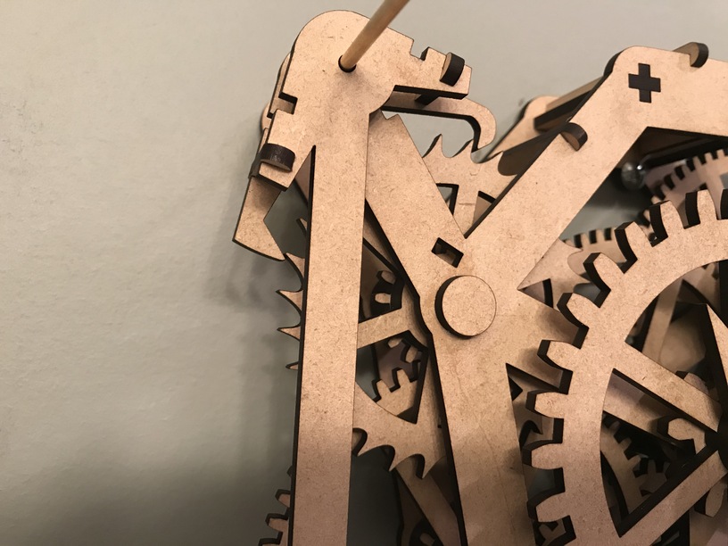
Are you talking about something more like this?
Where just tip of the tooth engages? And the impulse-face is larger and always engages (not allowed to slide past if the swing is too large)?
Yes. Although the impulse face (pallet) ends are where you’ll want acrylic or at least an acrylic inset on the contact points. Notice in the drawing how the ends curve vs being flat so that minimizes the amount of contact time on each swing. The other alternative is that super slick tape I mentioned that someone here found on Amazon & posted about last year. (I bought some at the time but have no idea what I did with it
… I was playing around with my clock, trying to make sure nothing was catching and everything was smooth. And I discovered that I had snapped the cross-axle on the minute hand.
It was still turning, but when I went to add wax to the pivot point, the whole thing fell apart…
So I will be printing a new axle tomorrow (it is to late tonight; I am going to bed…)
I printed the new cross-axle in acrylic to see if it will reduce friction (also because I already had the acrylic on the bed since I was trying an escapement out of acrylic.)
I haven’t fully tested it. I want to wait until I had the new escapement worked out before I put it all back together and hang it on the wall again.
But the gears all seem to spinning well. I cannot attest to if it is better with the acrylic axle yet…
Edit:
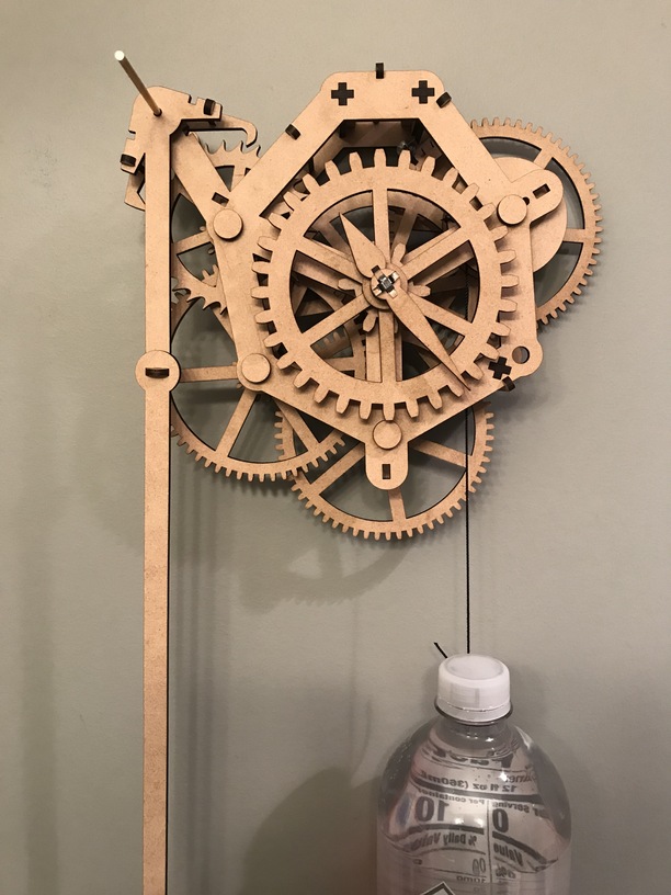
Here is the next escapement I will try:
It is still using the cross-axle to join to the pendulum, but if this version has issues too, I will switch to brass-axle join it with the pendulum under the pivot.
For this test I removed the face and the hour-gear (to reduce energy consumed in the drive-train). Before the video began, the clock had been running for a couple of minutes. By now, the clock has been running for around 15 minutes! Progress!
I will count this as a success if I can get it to run with the hour-gear installed, but for now I am just enjoying the quiet “tick” of the clock…
Edit: I am afraid to add the hour-gear back in… I don’t want it to stop…
Another thing I learned when I was testing out the acrylic-axle is that the kerf on the acrylic is wider than on the draftboard.
I can pressure fit the draftboard-axle without glue, but when I made it out of the acrylic it was loose and would not hold together on the top (where the kerf is widest.)
After my huge success with the pendulum running for around half and hour, I discovered I was incredibly lucky with how the escapement engaged escape wheel. It was “loose” on the axle and offset.
Once I tried to “fix” the escapement on the axle, I ran into all kinds of problems… But, now that I know how it is supposed to work, and I have experienced it, I know what minor adjustments need to be made! (I think…)
I am trying to redesign the escapement again, based on what I have learned, and what I have experienced. (I am getting ready to test version four… and I hope it goes well.)
While attempting to test the escapements, the clock fell off the wall again.
It snapped the pendulum in two locations and damaged some the gear teeth where it fell… The frame held together this time, so no pieces went flying (unlike last time). But the clock just doesn’t seem to run the same either. I am sure something else was damaged and I just cannot see it…
It may be time to cut out a whole new clock. But I was planning on changing the pulley system anyway, so I will probably wait until I have that redesigned.
What I am hoping is the final design for the escapement is completed and has been testing very well. My current version of it is still draftboard, but the final version will likely be acrylic.
I redesigned how the escapement was connected to the pendulum. Now they both pivot on a brass rod and are connected at the edges to transfer the movement back and forth. I found that I was still getting to much twisting with the cross-axle and eliminated it. I still need to cut the rod to length and glue a cap on the pendulum.
I swapped out the huge paracord I was using for the pulley for some super thin nylon cord. It should have much less friction if it rubs on anything and I can wind more around drive-train-drum.
I still cannot get the clock to run for a longer period of time (like before), but I can see that it is because the frame is shifting again. The stabilizers I was using appear to have failed again, so I either need to cut some new ones or come up with a better design there as well. (I may cut some new ones until I can come up with a better design…)
This is part of why I also bought a GF. I’ve been working through the Inkscape tutorials lately and they have 2 really neat SVG’s of 2 different clocks at this link that are downloadable.
Probably not really help, just something of interest.
I have looked at a lot of different designs of clocks for inspiration for my own. I feel like each one has taught me something different. I will definitely check these out too!
Thanks!
Edit: I checked it out. They give some nice gear-ratios there. I would love to add more information to my clock (like day/night, day of month, or even month).
Have you tried any of these yet? I feel like they have left out some of the hardest parts, like the escapement and regulation. But maybe I am just doing this the hard way…
I just put my Plus on order yesterday. I was a driver for a very long time and am just now finding the time to follow my crafting desires so I am on a journey myself, learning as I go. As for the SVG from
Inkscape it was just something I stumbled upon that I felt was relevant to the thread. I’m glad you found it useful and gives you something to work towards.
I have a Plus too (though after having played around with it so much, I wish I went for the Pro).
My plan is to share these designs in the “Free Designs” section here once I get them working. So others can play with and learn about how mechanical clocks work too!