Here I will discuss my process and progress of attempting to make this with using only the . But if that seems impossible, I may try adding externally sourced additions like metal rods or bearings if needed.
I have been thinking about this a lot, even though it has been a very busy summer. I want to share my experiences and progress here like I did with my clock build.
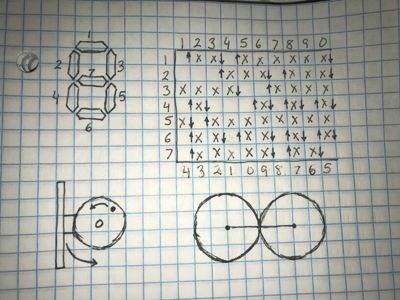
My first thought is to focus on a single line. If I can get that working it should just be duplicating the build so there are seven of them with different settings.
Two gears rotating opposite directions should be able to handle the “on” and “off” states of the line. One to trigger “on” state and the other to trigger the “off” state.
With ten numbers (0-9) each gear should only need ten arcs lined out on each gear. And if I can get the gears to push/pull a lever, I think I can use that to change the “state” of the line.
I have played around with several ideas for the triggers on the gears, but I think the strongest contender is currently a peg or catch sandwiched between two surfaces (I will probably make them both gears in an attempt to give the switch strength/stability.
Their size will need to be determined based on the distance I will need to pull/push the lever.
No, it is very much binary. Each line is either “on” or “off” in a very binary manner. My attempt will be to make the binary states controlled mechanically.
Thinking cam may work best as binary either pushing against gravity for a one and not pushing for a zero. Also, some numbers will need only a one or nothing as there is no 36 o:clock
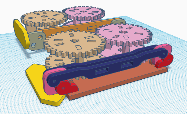
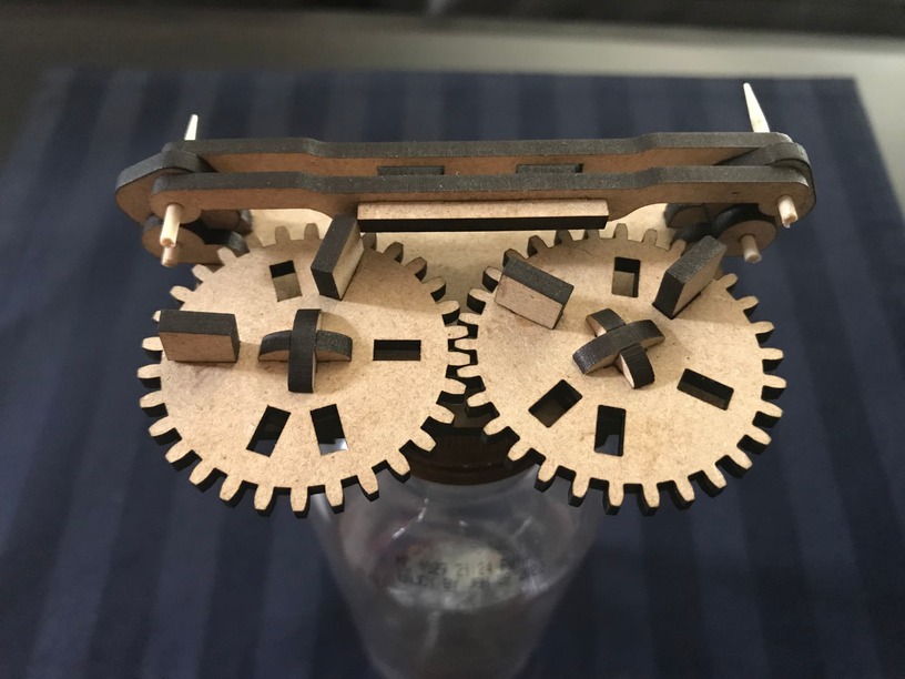
The back model is with the line active (up). The front model is with the line inactive (down).
I also think my timing on the up/down needs to be adjusted. The up needs to occur at the front of the “period”, but the down needs to occur at the back. I currently have them in the middle, essentially.
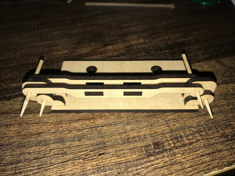
Once I have cleared all the “virtual” hurdles I will start prototyping.
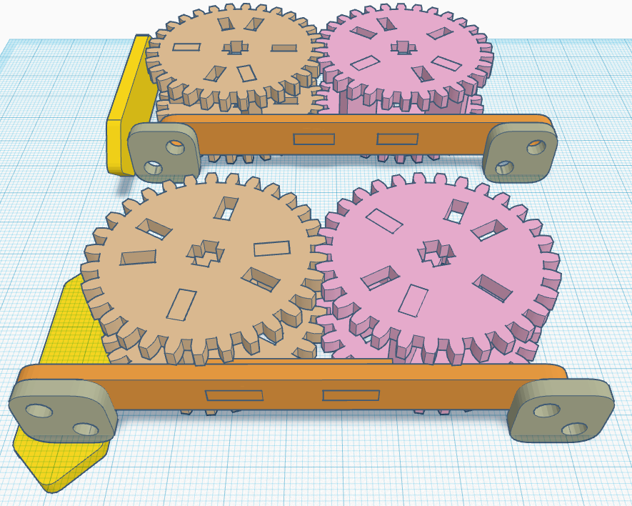
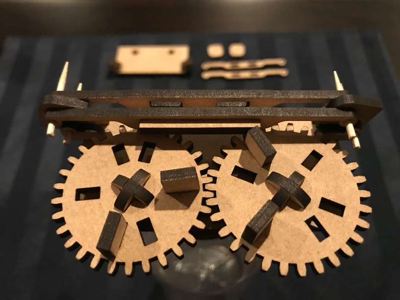
Pushing the rocker is working, but I feel like it is requiring to much torque. The initial design was definitely over-engineered, so I removed the top gears. They just were not necessary.
I am only getting about a 40-45 degree shift on the rocker, when I was originally planning closer to 90 degrees. So either the rocker-hinge needs to be smaller to account for the shorter distance, or the arm needs to be longer with larger gears to push it.
I am liking where this is going though. Just like with my clock, I will need to reduce friction everywhere I can, so this will likely end up using acrylic also.
I also need to adjust the catches; if they are not completely straight the push is not completed all the way. But this is looking feasible. I need to figure out the gear train and how the sideways orientation is going to work.