Not sure what they told you for how to figure out slot widths, but this is the law of sines in action.
In this case, it’s a 30/60 angle, so your slot width is sin(60)/sin(30) * material thickness + kerf adjustments.
To make it easier, it’s 1.732 x your material thickness and then do kerf adjustment to suit your “how tight does this need to be” needs.
For kicks, I built a spreadsheet and calculated for number of sides of a polygon to get the correct gap width, here you guys go… pardon the formatting, discourse doesn’t love tabular data:
# of sides Inside angle Gap width factor
3 60 1.732
4 90 1
5 108 1.376
6 120 1.732
7 128.57 2.076
8 135 2.414
9 140 2.748
10 144 3.078
12 150 3.732
So, let’s say you wanted to make a 12-sided “ring” of pieces that need to slot into each other, they’d hit at 150 degrees, and so the gap should be 3.732 x your material thickness.
Note for math nerds
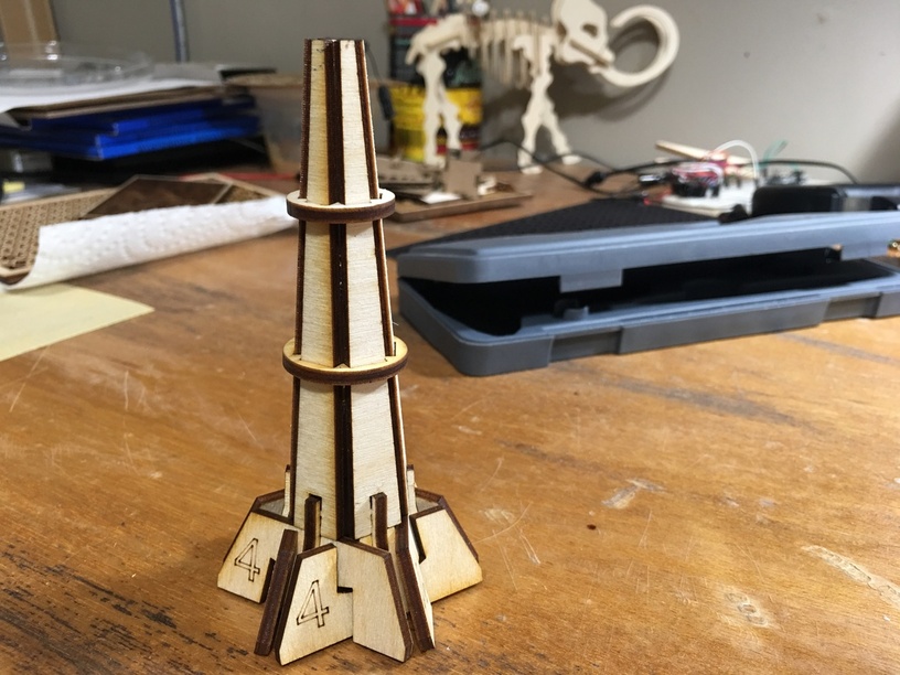
This only applies for material junctions that are orthogonal. If you start canting your faces from each other, slots get weird quickly. While you can suffer through it with trig, I found it was easiest to use 3d modeling software (Sketchup in this case) to derive the slot size and shape. Below is a picture of a 15-degree canted hexagonal slot system… The base pieces (“4”, as in 4th iteration of kerf testing) are canted in at 15 degrees, as such the slots are not rectangular.