I suppose you probably could. The key is actually how you phase the drives shaft which I totally forgot to mention. Each leg pair drive piece needs to be angled off from the one before it some amount so that the legs are doing different things at the same time. For 2 leg pairs you’d want them to be 180 degrees off, 3 leg pairs would be 120 etc. I haven’t studied two leg pairs together to be sure that they’ll maintain balance but now that you mention it and I googled two probably would work
3 Likes
This has been my issue with ALL of the F360 tutorials. Almost every single one that I’ve gone through has skipped something. And that one thing has really soured my experience with the tool and making me feel like it’s not for me.
However, @markevans36301 has been working on a tutorial that I’m excited to give it a try and jump back into F360 modeling.
5 Likes
I’d love to do a tutorial but I’m sure @markevans36301 will have done way better than I could. At this point I do 75% of the modeling in my head before I ever put it into the computer which results in me sitting in front of the computer staring off into space and people asking if I’m alright and it’s hard to say “yeah I’m great I’m just manipulating an imaginary model in my head to make sure I have the dimensions right before I waste time putting it into the computer” I’ve already got the mind model for the wind powered modifications ready for when I get back to the computer 
7 Likes
Do let my work deter you there’s still plenty more to do! 
1 Like
I’ll be on vacation till next weekend but if you guys do want help I could probably lend a hand with solid modeling stuff. Shoot me a PM at some point if you do
1 Like
I would really enjoy going through more tutorials to get me comfortable with F360. I have a background in Technical Writing and spent the last 6 years as a Systems Test Engineer. I can go through your tutorial and give you feedback as to how it reads to a new user and how to phrase things to make more sense to someone who has ZERO assumptions about the tool.
There are too many F360 tutorials out there with missing steps or assumptions that make the tutorials next to useless to the beginner user.
4 Likes
I’ve done a series for the absolute beginner, anything beyond that is fair game/ won’t repeat work. I’m doing some minor rewrites right now but should be caught up by the time you get off vaca.
1 Like
Yes, 180 degrees off, but also wide enough for static stability. I built one here with two leg pairs.
4 Likes
AWESOME!!! They’re so elegant when they walk I love it. I really like the “rhinoceros” species with the wide legs like that. We had to build drill powered vehicles in college and I tried to convince my team to build one of these and they refused to let me “talk [us] into doing another one of your off the wall insane ideas” but come on look at that thing it’s so cute!
2 Likes
I like this guy’s use of the mechanism.
https://youtu.be/2C3_7cd-jhg
12 Likes
Very cool! I tried 3D printing a Strand Beast from Thingiverse files but the printed parts varied too much. I’ll bet acrylic cut with a GF will fit together much better and be faster to make as well.
6 Likes
I actually started this design with 3D printing in mind but the precision just isn’t there. It’ll look and function so much better from lasered parts
3 Likes
Very cool @millersw.628. I’ve always been a fan of Theo Jansen.
I will totally be trying out your design in the future.
2 Likes
Very cool. I’ve been thinking about trying to work out some kinetic desk sculptures to take advantage of the little desk fan I always have running.
3 Likes
After working on a few other projects, I could get around to the file. Thanks again @millersw.628. This is cool. I have a bunch of big box store plywood I’m testing it on. Here are a few comments about the file itself, which fundamentally is usable as is.
The text was left as text and when you import it, it is stripped off but still has the text boxes. You can just ignore that operation, but the big boxes that show up muddy up the workspace and make it harder to position. Converting it to engravable vectors is easy enough and that would help the identification, but would definitely at a lot of time to the print.
It was easy enough to convert the text to paths by selecting one and then select object by type.
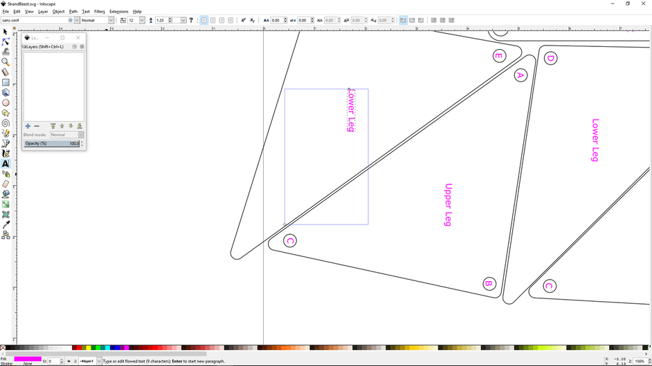
You can see in the Inkscape screen capture the text box.
As for the SVG, a couple things that are helpful. One is if you make the document property landscape 20 by 12, you can do a little easier packing ahead of time for processing the cut. As it is you have it fairly well nested, but since it is portrait mode, that means you either have to reposition or rotate in the GFUI or in the design software. So thinking landscape mode for positioning will help later on. In the end, the file works fine because the objects are good to go for cutting, but just something to think about for efficiency.
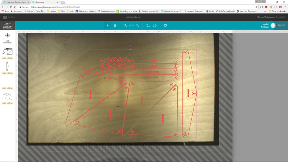
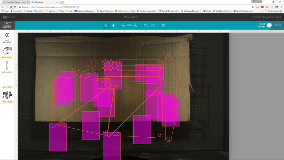
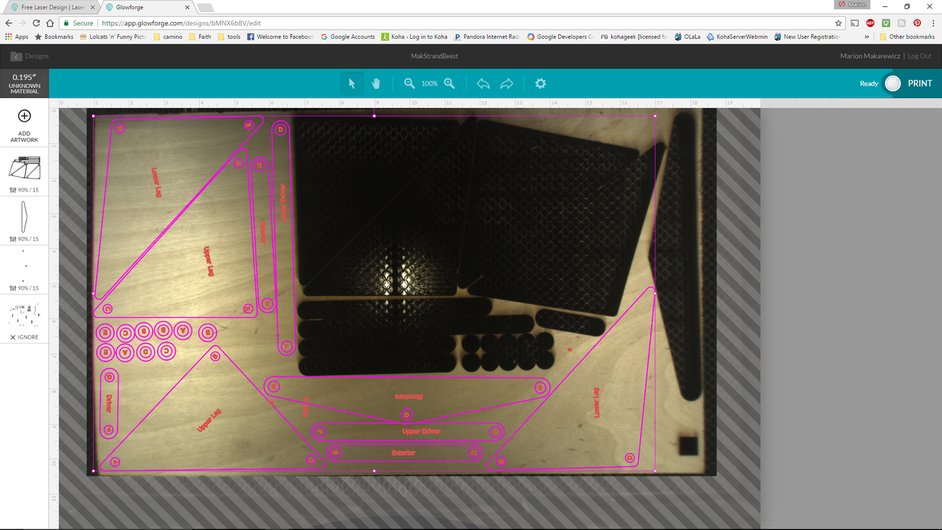
Here it is in the GFUI. a 12 minute print.
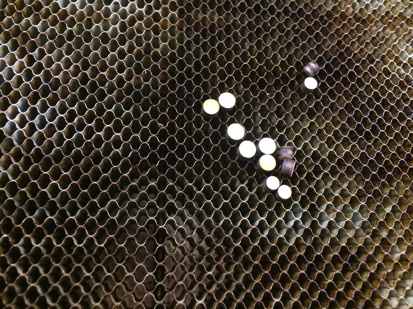
And I’ll have to think of something to use the hole cutouts for.
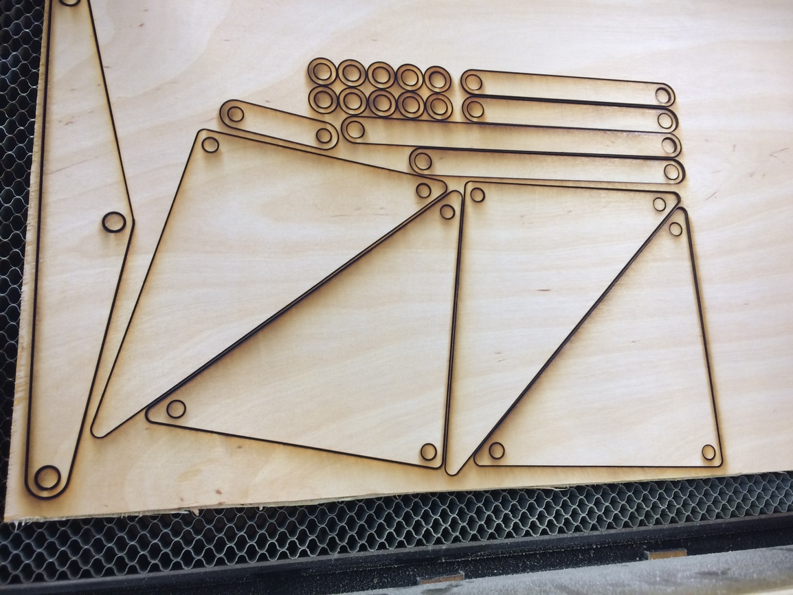
And here is the second print. Would have been easier to pack it either first in Inkscape or in the GFUI before printing. So you have scaled this up so that you can print two complete leg sets per available print area of the bed on my prerelease. So that works pretty cool. For the other prints, I’ll go ahead and do the nesting in inkscape since it is a bit faster and then can save the file nested.
Now the fun part of assembly. This is complicated. Congrats on this and thanks again.
35 Likes
Some excellent advice on planning specifically for the Glowforge, and applicable to other apps as well. Thank you!
3 Likes
Thank you so much! If you have any assembly questions shout, and again it only really works in theory so I hope it does work
1 Like
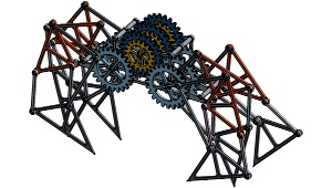
As I understand it, the pins fit tight and hold to the lower and upper leg triangle pieces and then are free to turn in the bigger holes of the driver, linkage bars. Here is an OnShape model of this with drive gears:
https://cad.onshape.com/documents/5797bab3e4b0bec2524e31f9/w/291d72f513c63fc9988ab2c1/e/f037c05493d5aefa86e83fdb
7 Likes
Did I goof up which ones are loose or are they all loose? I had intended for the triangle pieces to be a tight fit
No. You are good. They measure .255" in with the calipers, so that’s the result of the kerf. Need to pick up some 1/4" dowling or rod. I have a bunch of rods from old printers and copiers but none of them are 1/4". They will work though for some of the other connections, I hope.
1 Like