The first and most important thing I learned while going through this process is, strangely enough, not to worry about it too much. We can adjust to get a tighter fit, but the truth is I have measured 5 sheets of PG Medium Draftboard and they vary from 3.12 to 3.29 mm in thickness, so worrying much about whether your kerf is .1mm or .15mm is a rabbithole you don’t want to go down. I can only imagine it varies even more with other wood sources. Ballpark it and move on with your life. Ask me how I know that… That said, there are two primary schools of thought on doing Kerf Compensation while using Fusion 360. One way is to put it right into the sketches as a parameter, which is great because simply changing the value will change the kerf, making adjustments super easy. I had two problems with it, the first of which might just be the way my brain works. In case I’m not the only one with this issue I thought it might be nice to present an alternate way that might be an easier way for some. I still use a parameter, but I employ it graphically and not in the sketches.
The problem I have with sketching kerf compensation is I always seem to screw up if I’m adding or subtracting kerf loss when sketching because I need to see it in 3D to get it consistently right. Sometimes I push the dimension in the wrong direction in 2D… The other problem is the way I use Fusion 360 I let the computer figure out the slot dimensions. Said another way, I like to sketch the side of a box for example, and use a “combine” function to let the computer figure out where and how wide to cut the slots for the tabs I sketched on the sides. Here’s some photos to possibly explain this better.
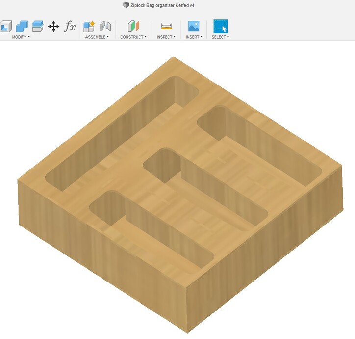
Here’s a ziploc bag storage box I made because SWMBO asked for one.
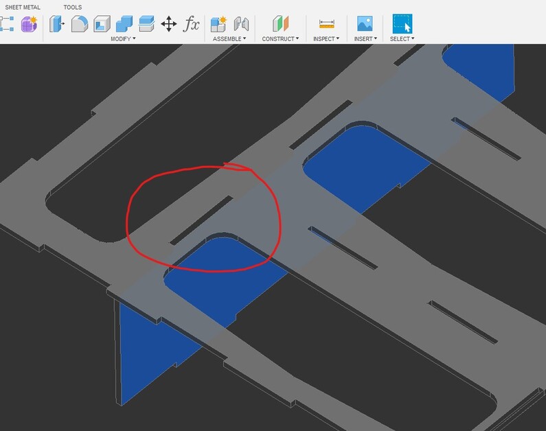
I use the “combine” function to get Fusion 360 to cut the slots for me. Of course once that’s done they are going to be a bit too big, because of the missing material cut by the beam (the
aforementioned kerf).
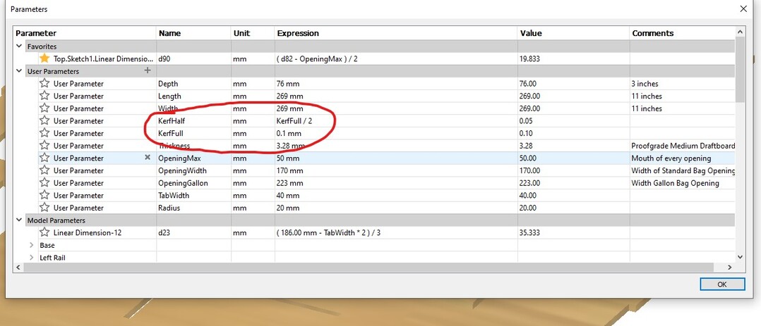
The Kerf on my machine, through PG Medium Draftboard at whatever pews and zooms are predetermined at GF HQ’s is about .1 mm total, which is .05mm on each side of a slot.
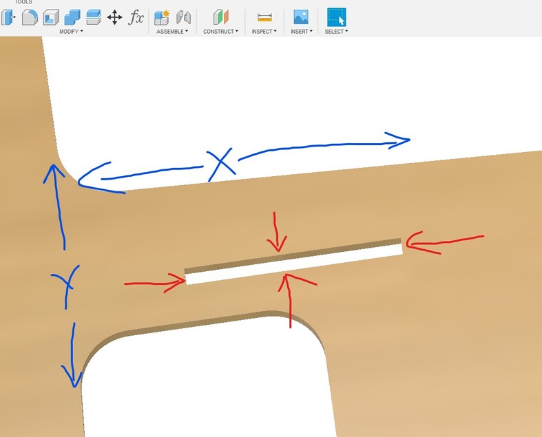
With the slot “cut” by the software we can see a 2D plane overlaid on it, with both a positive and negative X axis, and a positive and negative Y axis. To compensate for the missing material, each of the four sides must be pulled in by half the kerf value, which is the aforementioned .05mm. Thus, each axis of the slot will be tightened by .1mm, the kerf compensated and much if not all of the slack gone which makes for a nice box which is easy to assemble and glue up as it holds itself together a bit.
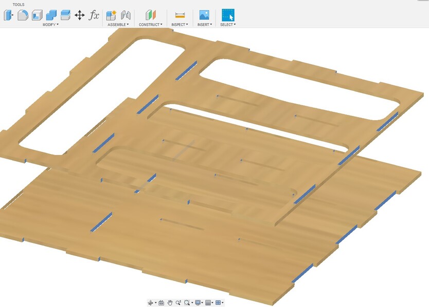
It is then (for me anyway) easy to see the whole structure of the box. Here you can see that every side of every slot in the whole box needs to move a bit (half the kerf, .05mm). Once each of the faces that needs to move to tighten the slots as been selected, and this is super important, right click and create and name a selection set.
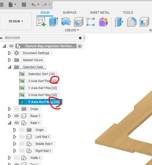
I did a selection set for each of the slot faces which needed to be tightened, and it’s easy to see if any faces are missing because they should all be equal. In the case of this box, I had 32 faces for each of the four axis’. If I missed any face, it would be obvious right here and would be easy to track down.
At that point, all that needs to be done is to go back and click each of the four selection sets, and do a “push/pull” with the parameter you set for half the kerf (again .05mm, in my case, for this material, ymmwv). It is still a parametric function, so if you find the slots are too tight or loose for your liking, a quick adjustment to the kerf parameter will adjust them. I only kerf compensate in the slots, not the tabs, in order to keep confusion to a minimum. Hope this helps someone.