The Glowforge isn’t cutting the way I expect it too.
So I’ve finally had a little bit more time to experiment with the Glowforge. I was creating a spam slicing device and noticed that my parts didn’t press fit. To calculate the kerf, I cut out a square and took the difference between the cutout and the hole and then divided by two. The Kerf came out to just under 0.1mm for the thick pg acrylic sheet.
I thought I would do test cut to see if I calculated the Kerf correctly, and now I’m more confused than before.
Here are the results.
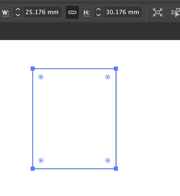
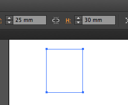
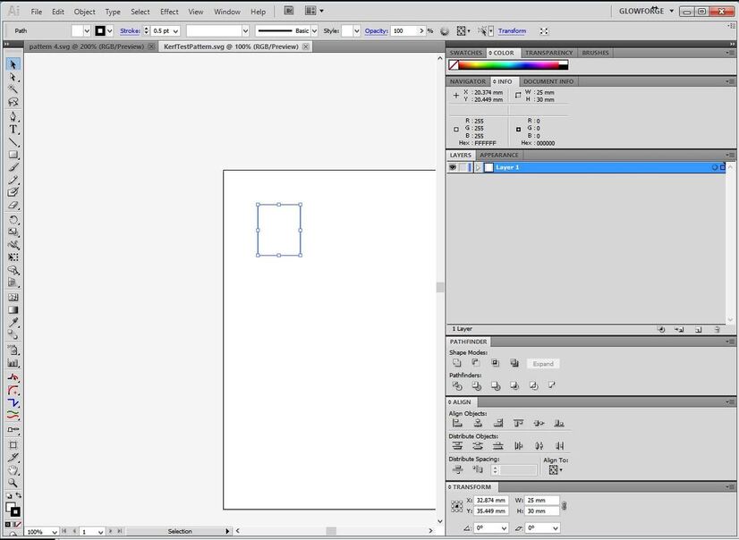
I created a 25mm x 30mm shape in illustrator and sent it svg to the Glowforge.
I don’t think the Glowforge is being straight with me.
Here are my results and they don’t make sense to me.
Cut piece measurements
Top edge - 24.75mm
Bottom edge - 24.76mm
Left edge - 29.83mm
Right edge - 29.91mm
Hole
Top edge - 25.02
Bottom edge - 25.02
Left edge - 30.14
Right edge - 30.21
I would expect the top and bottom numbers to be similar and it should be true for the left and right edge, with maybe 0.02mm variation.
Another thing that didn’t make sense is that the Top and Bottom edge of the hole is very close to 25mm but I was expecting it to be much larger because of the kerf (maybe by 0.1mm).
Am I going about this all wrong or does anyone also suspect that my Glowforge is not being straight with me?
That’s what makes cutting things with lasers a bit challenging.
One of the things you are seeing with your measurements is that the kerf created by a laser burn does not run perfectly perpendicular when viewed in profile. It is slanted.
There is always a larger kerf measurement at the surface of a cut than there is at the base when the laser is focused at the surface of the material. It’s because the beam is actually shaped like an X, with the focal point at the center of the X. The intensity is greater at the center, and diffuses more as you get farther away from the focal point. So it burns more material away where the intensity is the greatest.
You can try just using an average of the two measurements to try and figure something out that works, or just do a few tests with a small 20 mm tab and slot file to determine the adjustments that make your tabs fit into your slots tightly. Or you can try varying the focal point to the center of the material to see if it gives you more uniform surface and base measurements.
Of the three, just doing a couple of test cuts is probably going to get you the best results. When you have determined what the kerf adjustment is for a particular material, it gives you a good starting point from then on, for that material.
The top and bottom edge gives me an estimated Kerf of 0.135( 0.27/2 ).
The left edge gives me an estimated Kerf of 0.155( 0.31/2 ).
The right edge gives me an estimated Kerf of 0.15 ( 0.30/2 ).
The Kerf doesn’t appear to be too far apart so I don’t think that’s my issue.
I’m guessing it’s somewhere between 0.135 and 0.155.
I think the problem is that the laser isn’t cutting on the line like it should. If it did cut on the line then the cut piece would be approximately (25mm - Kerf by 30mm - Kerf) and the hole should be the opposite( 25mm + Kerf by 30mm + Kerf but this doesn’t appear to be the case.
Another thing to note is that since my top and bottom edges are measured to be 25.02 then the laser is cutting way inside the line.
Hmmm,
I am using an old version of illustrator, cs6.
Even with those numbers my measurements don’t make sense.
The measurement of the hole would be larger than what I have.
Would be nice to be able to see the measurements in the Glowforge UI.
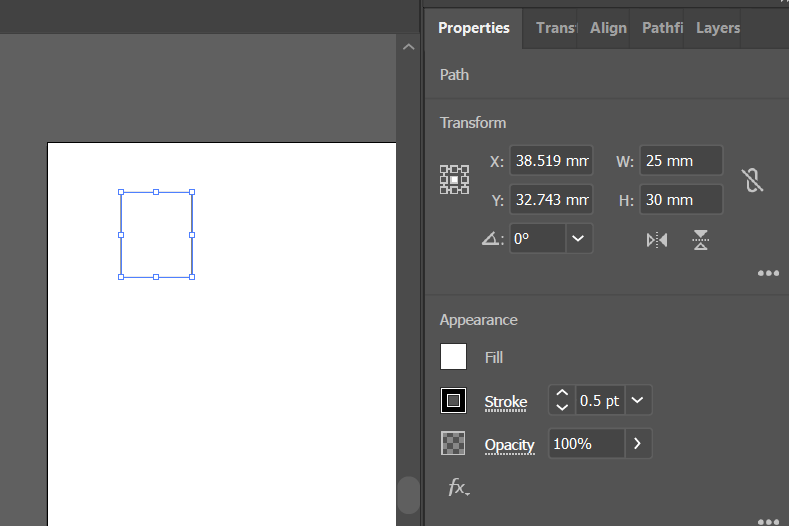
I also opened it in Graphics for Mac and I’m seeing 25mm x 30mm.
Interesting - I found an option in Illustrator I didn’t know existed (or know that I had enabled, at least). My preferences had “Use Preview Bounds” enabled and that was figuring in the stroke size.
Now that we’ve got that figured out…
I just poured first cup of coffee, so I maybe should wait to reply. I know that the document is saving as pixels (the SVG is defining your shape as something like 70x88 pixels). And pixels are going to change depending on the program they are being viewed in (Illustrator uses 72 pixels per inch).
So I wonder if you don’t have some kind of scaling thing going on.
I use inches for all of my stuff (blasphemy, I know). But I set everything up as a 20”w x12”h artboard. This does a couple of things - it provides absolutel positioning based on the file and it also establishes a view box of a particular aspect ratio that the Glowforge can determine proper scaling (if units aren’t defined or arbitrary units like pixels are defined).
Yeah, but that’s nearly a decade old now. While one wouldn’t expect something simple like measurements to change, AI’s interpretation of svg files may have.
For another data point. I also opened up in AI CC2018 and get 25x30. I also notice your path has both a fill and stroke which I have seen cause issues before.
I suppose one could set up a file with two squares laid directly on top of one another. One with a fill, one with a stroke. Engrave the fill and then score the stroke and that should give you an idea. The fill/engrave is going to engrave all the way to the shape boundary/vector path, and then the stroke is going to cut right on the vector path (you can see the set up if you go to view outlines in Illustrator).