You’re quite right - that was a subjective statement. My bad.
Since the settings on the last update were made available to all of us and I’ve tested them on the PRU, I’ve noticed a much tighter fit due to the currently created kerf on Proofgrade materials. BUT, it is based on a PreRelease unit so I have no idea if the same holds true with the Production units. So everybody ignore that statement.
Either the PG material varies more than GF thought or the Glowforge varies more than they thought, or the concept is flawed. In either case it isn’t user error so either the PG or the GF should be refunded.
Sorry to hear things didn’t turn out right, I have a few quick questions for you.
Can you let me know the date and time of the print?
Which type of Proofgrade maple were you using, hardwood or plywood? Have you had similar issues with any other types of Proofgrade material?
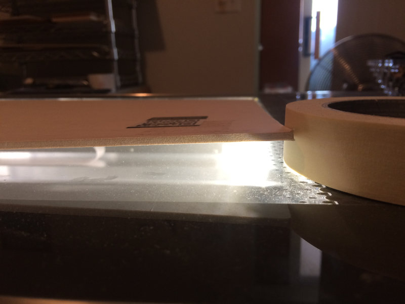
I’m getting much tighter kerfs on PG maple plywood, but combine that with material warp and I’m basically just using custom settings for everything on maple ply. I’d suspect the dry desert climate here is not playing nice, here’s a shot of an un-used sheet of PG maple ply, been here about 8-10 weeks (it’s the Starter Kit material). That’s a 1" wide roll of masking tape for reference. Now I can’t say that the wire steel shelving I’m storing materials on is completely flat, but it’s not 1/2" out either, and it does sit with all 4 feet contacting the supporting surface so I know it’s not racked out.
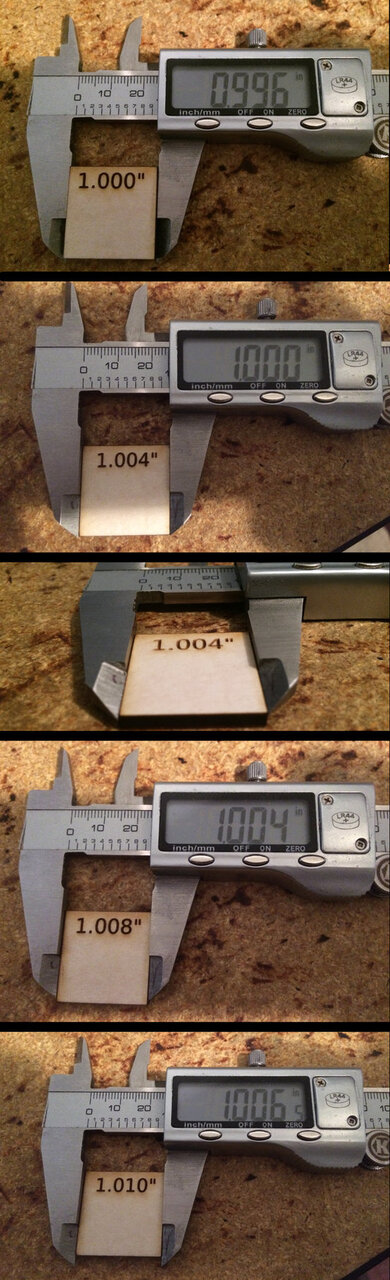
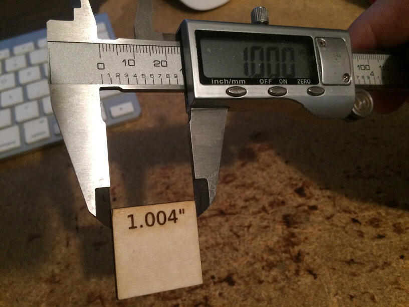
If you open the pic there are several samples shown. For the most part those measurements are between the middle and bottom of the kerf. If I line up the back of the piece with the rear face of the tines on the caliper, some of them are dead-on to the numbers printed on the piece. Others are at -.004" average.
Those will be the narrowest part of the kerf by & large. It “channels” into the material ablating the top to get further down which means the top tends to be wider than the bottom.
Mine is less too generally but only .007" - in 1/8" PG Ply. A lot depends on material, power and speed used to cut. Lower power, faster speed that still cuts results in a smaller kerf. Higher power, lower speed results in larger kerf. And the low speed high power multi-pass cuts are the worst
I’ve also found my use of the calipers leaves some variability as well depending on how much muscle I use when I close the jaws. Yours just looks lots smaller than I’ve seen before.
I put magnets on everything I can now just to make sure it is as flat as possible after I noticed a big piece was slightly bulged from the way I had it stored.
To truly measure the total kerf, wouldn’t you want to measure both the exterior of the square cut out, and the interior of the hole left in the sheet?
The difference would give you the total kerf (times 2) the measurement of the cut-out piece then shows the alignment of the cut within the kerf.
For example, if the path being cut is a 1" square, and the actual kerf is 0.008, one could have these variants or anything in between:
Variant
Outer
Inner
Kerf outside cut
1.000
1.016
Kerf evenly inside/outside
0.992
1.008
Kerf inside cut
0.984
1.000
I seem to remember some design tools apply automatic kerf correction by shifting the cut path slightly? It seems without measuring both, you won’t know for certain that the cut asked for was dead center in the kerf?
Edited: Oops nevermind, my mather wasnt working right LOL.
Depends how you want to set things up and where you want to make adjustments but typically if you adjust both mating parts by 1/2-kerf, they’ll meet up OK. If it’s wood you can press fit them, if it’s plastic you better give a little breathing room because if it’s dead-on, they wont fit, but if the material gets a little on the melty side with heat (like acrylic) it could still be a loose fit.
I’m hesitant to link this here because I recorded this last night with all my ignorance on display. I had not read any forum threads about warped materials and I don’t know nothin’ 'bout wood, so I’m going through this super naively. But that was kind of what I was going for: what happens if you just follow the directions without thinking about it too hard. (Spoiler: you fail) Also, my style of recording raw stream-of-consciousness thoughts as I go through it, now that I watch it back, sounds really whiny and complainy. Now that I understand that all wood warps and it’s not a big deal, I’d take most of this back.
Anyway, dropping it here because it’s kind of on topic and demos a sheet of warped-out-of-the-package plywood and a failure to cut through using default settings (including cutting the outside first). Easily avoided with some magnets and/or tweaking the cut order, but I also feel like the software could do a better job.
It’s been a little while since I’ve seen any replies on this thread so I’m going to close it. @adrianf if you still need help with this please either start a new thread or email support@glowforge.com.