Graphics problem

I’m trying to make an arch-topped picture frame, shallower at the top, so that the glass slopes down.
It’s in two parts - a lid like a standard frame, and a shallow back, with the top edge, supporting the glass, lower at the top than the bottom.

Lid done, so it’s the back that’s the problem

It’s to be made using thin(2mm) plywood, cut on the laser.
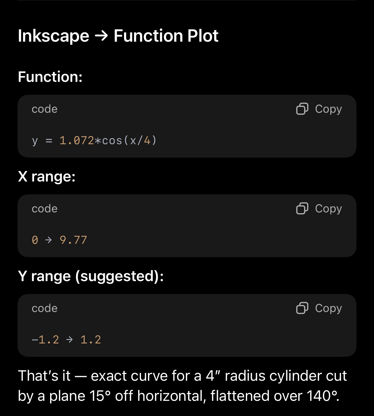
I’m using Inkscape to generate the graphic, but my problem is one of geometry/node manipulation.

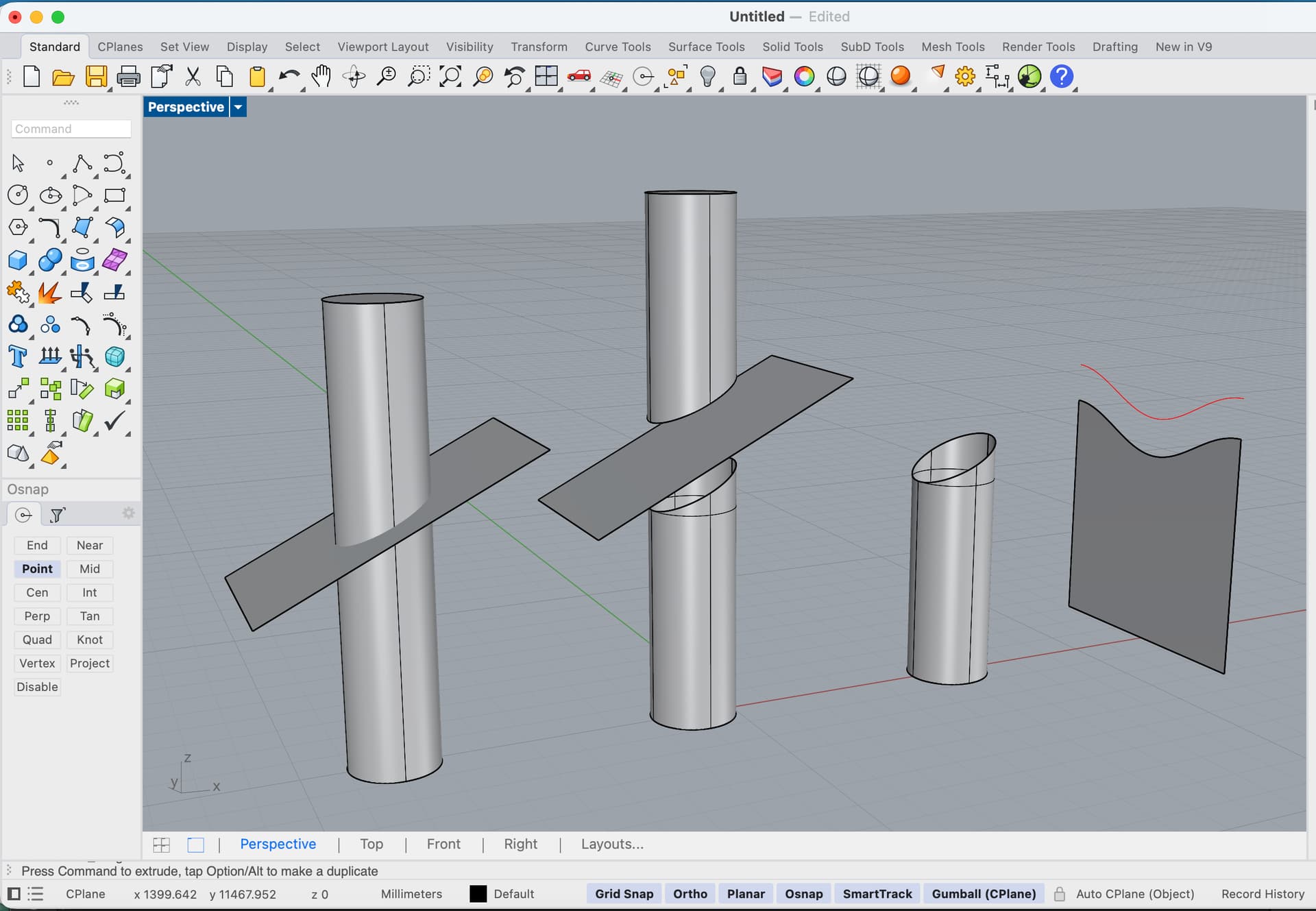
Think of a short cylinder.
Now make a slice through the cylinder, half-way down, and at a shallow angle to the horizontal.
Then make a pie-shaped slice down through the center of the cylinder, at 140 degrees,
and it’s the red surface in the drawing that I am trying to draw.

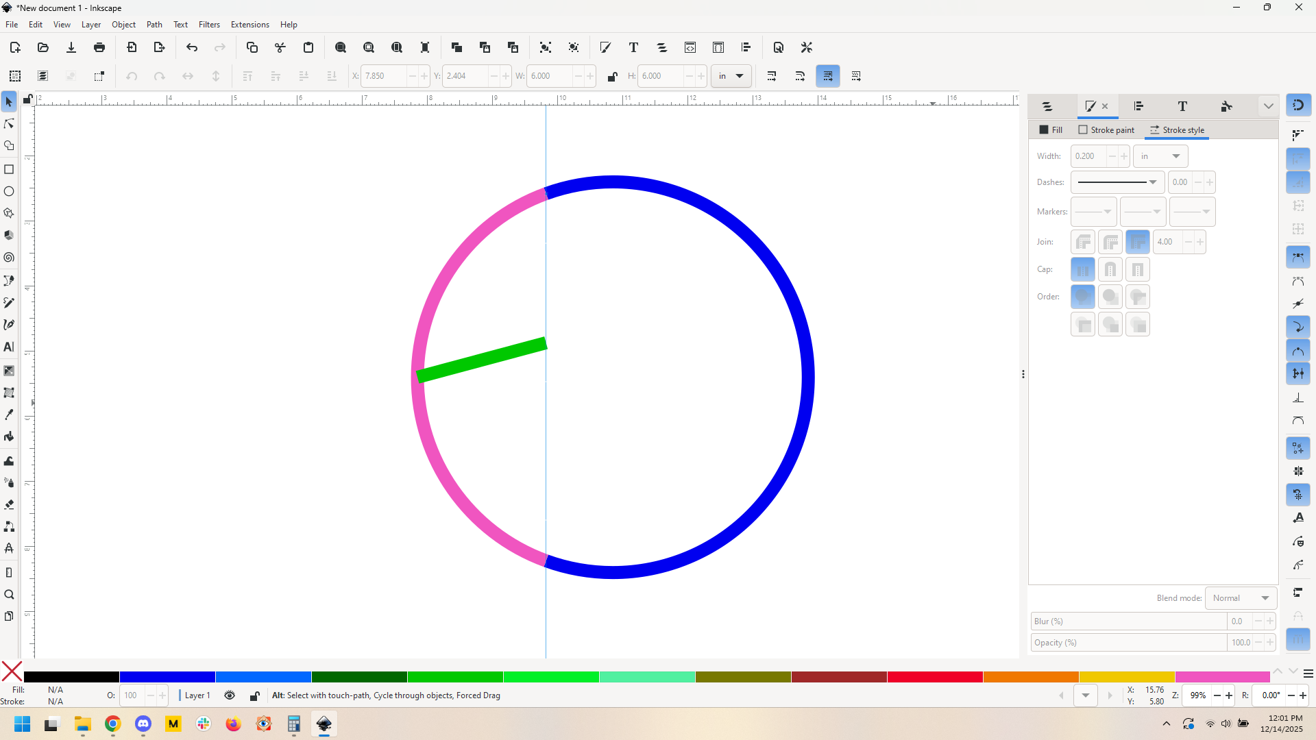
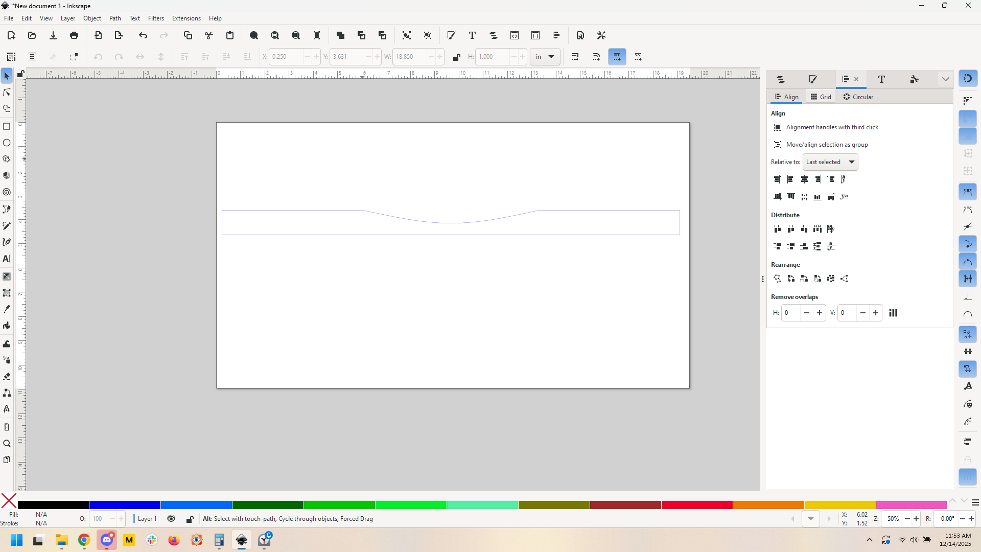
If I start with a long rectangle in Inkscape, convert it to a path, then pull the center of the top edge downwards, the resulting shape, when wrapped around a circular former, does not produce a top edge that is a flat plane.
I’ve tried using the node control tools, but can’t achieve an accurate result.
I’m sure there must be a mathematical representation of the shape, and/or a way of achieving it in Inkscape.

Any suggestions welcome.

georgian_wall_2

2 Likes

I’ll answer what you asked first (how to do it in inkscape) and then I’ll tell you how I’d do it.

The shape is a partial ellipse. (Cross sections of cylinders are ellipses) To know the actual shape you’d need to know the angle at which you want your flat plane to lie.

Unwrapped this would become a 140 degree segment of a sinusoidal curve.

I am not at my pc so I can’t test it but I think you’d use the function plot extension and use function

You didn’t constrain your requirements enough to get a firm answer so I assumed a couple of things:
4” radius cylinder
15 degree plane angle from horizontal

Then because math is hard I asked GPT to help me work out the formulae. GPT is very confident but can be super wrong so I’d recommend testing with something like cardstock to get this dialed in:

Also you’re talking about bending a material which may also introduce inaccuracy.

This is all fine and will probably get you close. Then it’s just a matter of using that curve as the top of your rectangular wall segment.

THAT SAID.

If this were my project? I’d make a cylinder, then I’d measure how low the lowest point is on the outside of the cylinder and 140 degrees on the top edge of the cylinder. Then I’d just take it to my disc sander and grind the material off. It’ll be a perfectly flat angled portion and even be beveled correctly.

Sometimes a laser is just not the best tool.

No disc sander? You could do it with a nice flat surface and sandpaper glued to it. You’ll have to be careful but I bet it’d work. A disc sander will just make it much much faster.

11 Likes

This kind of thing is what CAD tools are made for! It’s been a while, but I’ve used Fusion360’s bending tools to translate between curved surfaces and flat cuts.

6 Likes

Yeah I use sketchup for stuff like this… but the question was how to do it in inkscape.

There are even easier ways to do it if you can get a high quality sine curve svg. Then it’s just a matter of carefully scaling and aligning stuff.

4 Likes

You can do a lot of things in inkscape, it’s true, but as you pointed out in your reply there are sometimes better tools for the job! :grin:

I often have to remind myself to step back and consider if the tool I’m holding is the best choice.

6 Likes

Thanks for your reply. It’s given me a good starting point. Now I need to play with it !

John

4 Likes

@timjedwards is spot-on. Using a 2D illustration program to investigate something that CAD software is best equipped to reveal is a fruitless endeavor.

Having slept through my fair share of geometry & trig classes, the only highlights that stuck include the notion that if a cylinder were sliced by a planar surface, the cut edge forms a sinusoidal or parabolic curve.

This is the unfinished CAD example started last night before dozing off…

The UnrollSrf command in Rhino3D demonstrates how you’ll never get a straight line from this planar cut UNLESS it’s perpendicular to the cylinder.

4 Likes

This can be done in inkscape much more quickly by just deductive geometry.

Believe me there are cases when 3d software is the way to go:

But for this? Easy enough.

4 Likes

OK So I decided to try this now that I am at my machine, Ill time myself and see how it goes.

Not gonna fool with functions so I go find an svg.

Cool.

Gonna make 2 assumptions: 6" diameter frame, 1" frame depth, with a 15 degree angled section.

OK, going to do it and see how long it takes.. done. Ten minutes, while figuring it out.

Here’s what I did.

First, some math: 2* pi * r, 18.85" total frame circumference. 140 degree angle, so length of “cut” edge (140 degree arc) would be 140/360 * 18.85 = 7.23"

OK so now we need a segment of the sine that is 140 degrees, that’s easy enough:
Get our sine, measure its width. Mine was 9" so the segment we want is similar to the way e figured out the cut edge. 140/360 * 9. I make a rectangle that is that wide, then use alignment

and cut path

That’s the sine wave. Now we need to know how tall that sine wave needs to be. For that I make a scale circle (blue), cut out a 140 degree arc from it using a path at set angle (pink), then make a 15 degree line that crosses the width of the segment of the circle (green).

Therefore our sine chunk needs to be 0.529" tall.

Scale the sine portion to be that height, then align it to our 18.85" rectangle. Some quick path operations later and we get this:

And that should be our frame edge.

I still think a disc sander is the way to go here, but it’s definitely doable in Inkscape, and in ten minutes including time to work it out. If I were to start fresh knowing what I know now, it’ll probably be something like 3 minutes.

Of course this all assumes that I am right about the sine wave here and that the sine wave file from wiki is an accurate size wave (it’s wiki so I think we’re ok). I think I am, but I reserve the right to be wrong :slight_smile:

6 Likes

:+1: Hi evansd2,

Your general case is basically the way I’ve gone.

It took me a little while to figure out how to use the Inkscape ‘function’ tool, (perhaps about 20 minutes !), and realizing that I had got some of my original dimensions wrong, it came out pretty well.

No, actually it came out perfectly !

Thanks again.

In general, I don’t see any need to acquire the skills needed for other software. I’ve used inkscape for many years, but just had to add one more skill to familiar territory. I’m perfectly comfortable in working in a 2d program, as, though my products are generally 3d, my starting material is always 2d.

The problem always arises from trying to get the 87 yo brain to remember maths that I learned 70years ago !

John

6 Likes

Glad you got it figured out. I hope you post pictures of the end result, I’m curious!

6 Likes

This topic was automatically closed 32 days after the last reply. New replies are no longer allowed.